Connecting the motor
Connect motor wires to ‘M-’ and ‘M+’of terminal block T1 (BLACK)and T2(RED).
Connecting power wire
Fig.8
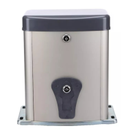
7.Electrical and control board
Fig.9
Motor: black wire to T1 and red wire to T2.
J1: transformer secondary(AC24V/3.3A)
external Push Button(J2,J3,J4):
Single Button(OSC and COM)
Three Button(K,G,T,and COM),
Photo beam(PE and COM)
Output DC power: 24 and GND
J5: solar panel(10W 27V) and charge Battery.
NOTE: Please put through the “J5”(Battrey) terminal, if you need use the sliding gate
operator.