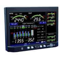
FAA Approved Installation Manual for the Report No 908
EDM-900 and EDM-930 Page 1 of 55 Rev I
Primary Engine Data Management System Date 1-18-2013
TABLE OF CONTENTS
1. Revisions ______________________________________________________________________________________ 3
2. Instrument Marking ______________________________________________________________________________ 4
3. Primary TSO Label ______________________________________________________________________________ 4
4. Operation and Abbreviations ______________________________________________________________________ 5
5. Dimming ______________________________________________________________________________________ 6
6. Locating and Installing the Indicator and Remote Alarm Display (RAD and Alert Light) ________________________ 9
6. EDM-900/930 Key information installation __________________________________________________________ 11
7. Routing the Wiring Harnesses_____________________________________________________________________ 12
8. Power Connection ______________________________________________________________________________ 12
9. Wiring Markings _______________________________________________________________________________ 13
10. Exhaust Gas Temperature Probe (EGT) Installation ___________________________________________________ 13
11. RADIAL Engine EGT_____________________________________________________________________________ 14
12. Turbine Inlet Temperature (TIT) Probe Installation (optional) ___________________________________________ 14
13. TIT for second Turbine Inlet Temperature ___________________________________________________________ 14
14. Using the Factory original TIT Probe_______________________________________________________________ 14
15. Cylinder Head Temperature (CHT) Probe Installation__________________________________________________ 15
16. Radial Engine CHT (spark plug gasket) _____________________________________________________________ 15
17. Outside Air Temperature (OAT) Probe Installation ____________________________________________________ 15
18. Induction Air (IAT), Compressor Discharge Temperature Probe Install (optional)____________________________ 15
19. Carburetor Probe Installation (optional) ____________________________________________________________ 15
20. Oil Temperature Probe Installation ________________________________________________________________ 15
21. Oil Pressure Sensor Installation ___________________________________________________________________ 16
22. Fuel Pressure Sensor Installation __________________________________________________________________ 17
23. Adding a non-primary gauge to the system ___________________________________________________________ 17
24. Fuel Pressure Sensor Installation __________________________________________________________________ 17
25. Ammeter Shunt Installation _______________________________________________________________________ 18
26. Load Meter Configuration________________________________________________________________________ 19
27. Fuel Level Sender Wiring Types ___________________________________________________________________ 20
28. Capacitive Sender Frequency Output Type Sender System_______________________________________________ 20
29. Resistive Output Type Sender System (Float type, most common) _________________________________________ 20
30. Voltage Output Type Sender System ________________________________________________________________ 22
31. Fuel Tank Calibration Setting Fuel Calibration Points _________________________________________________ 22
32. After you have collected your data _________________________________________________________________ 24
33. Fuel Flow Totalizer, Refuel Question _______________________________________________________________ 26
34. GPS Interface _________________________________________________________________________________ 27
35. Manifold Pressure (MAP) Sensor __________________________________________________________________ 27
36. RPM Sensor installation _________________________________________________________________________ 28
37. EDM-900/930 Specifications and Limitations_________________________________________________________ 29
38. EMI Radio Test and functional check:_______________________________________________________________ 30
39. Component Parts_______________________________________________________________________________ 31
40. Weight and Balance Data ________________________________________________________________________ 32
41. Pilot Programming _____________________________________________________________________________ 33
42. Programming the HP Constant ____________________________________________________________________ 33
43. Selecting Fuel Pressure Type (EDM-900 only)________________________________________________________ 34
44. Customizing Non-Primary Data (EDM900 only) ______________________________________________________ 34
45. K Factor______________________________________________________________________________________ 34
46. Adjusting the K Factor___________________________________________________________________________ 37



 To Next Page
 General