2.Installation of Scanner Unit > 2.1 Equipment Cable
2-3
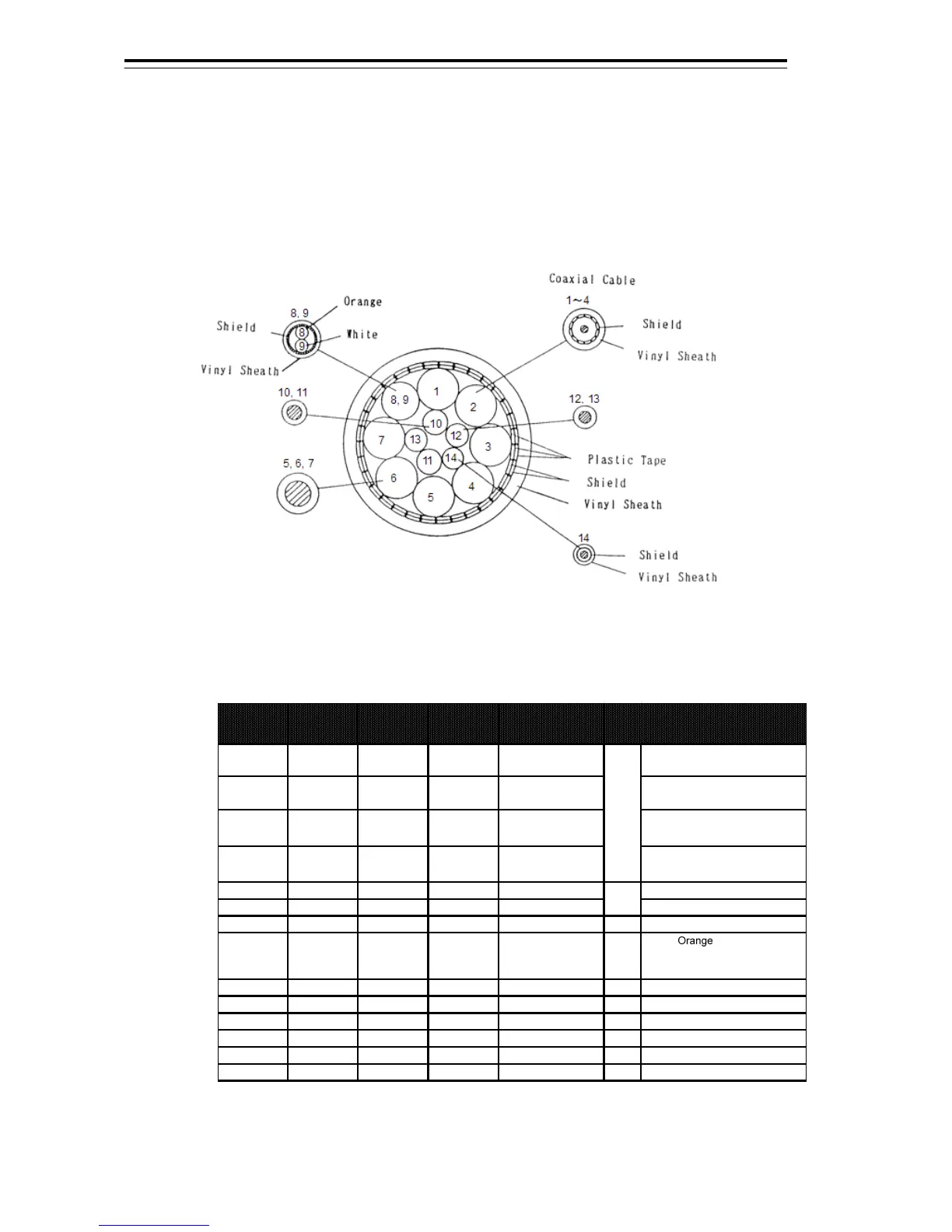
2.1.2 2695110056
This is a 14-core shielded composite cable.
This cable is used to connect a NKE-1125 type scanner, a NKE-1130 type scanner, a NKE-1632
type scanner, a NKE-2632 type scanner, a NTG-3225 type transmitter-receiver or a NTG-3230
type transmitter-receiver to the display unit.
Fig 2-2 Cross-sectional drawing of 2695110056
Table 2-2 2695110056 wire
Core (No.)
Cross
Section
(mm
2
)
No. of w ire /
φ
Color
Re m ar k s
1
0.5 19 / 0.18 Black 1 Coaxial Cable
Center Conductor: 1. VD+
Outer Conductor: 2. VD-
2
0.5 19 / 0.18 Black 2 Coaxial Cable
Center Conductor: 3. TRG+
Outer Conductor: 4. TRG-
3
0.5 19 / 0.18 Black 3 Coaxial Cable
Center Conductor: 5. BP+
Outer Conductor: 6. BP-
4
0.5 19 / 0.18 Black 4 Coaxial Cable
Center Conductor: 7. BZ+
Outer Conductor : 8. BZ-
5
5.5 35 / 0.45 Yellow 1. U
6
5.5 35 / 0.45 Green 2. V
7
5.5 35 / 0.45 Brow n
--
8
0.3 12 / 0.18 White
Tw isted pair cable
w ith Shield sheath
white
J832
Yellow : 9. MTR+
White: 10. MTR-
Braid: 11.MTRG
9
0.3 12 / 0.18 Orange
-
-
10
2 37 / 0.26 Red J832 13. DC+
11
2 37 / 0.26 Blue J832 14. DC-
12
1.25 50 / 0.18 Black
--
13
1.25 50 / 0.18 Purple
--
14
0.5 1 / 0.18 Gray
--
J832
TB838
CQD-2273
Radar Interface Circuit
maximum diameter 23.0mm
 Loading...


