3-3
3) Connecting the LCD monitor to the radar process unit
The display unit and the processing unit are connected by one cable.
(RGB video signal x 1)
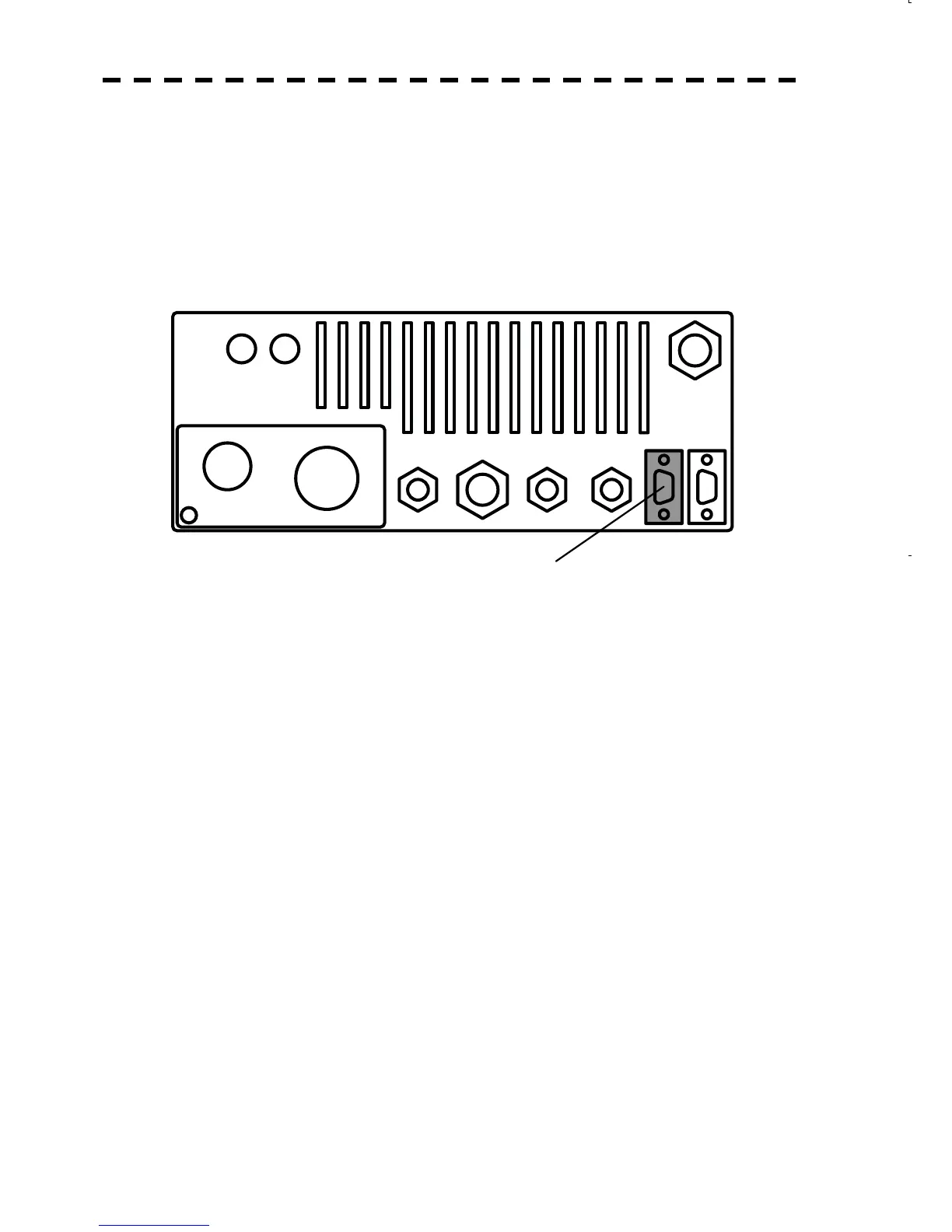
<1> Connect the D-sub15 PIN cable, extending from the LCD monitor (NWZ-164), to the connector for
which "VIDEO" is engraved at the rear of the radar process unit cabinet. Turn the control attached to
the connector until it cannot be turned any further.
<2> The power for the display unit is not supplied from the indicator.
Use a dedicated cable that is included in the package of the display unit for the power supply to the
display unit.
To the LCD monitor
(RGB signal)
NMEA
AUX
VIDEO
AIS
NMEA
GYRO
COMPASS
GPS KEY BOARD
E
POWER SCANNER
F3F1 F2
 Loading...


