8.4 REPLACEMENT OF MAJOR PARTS
ņ54
8
yyyy
yyyy
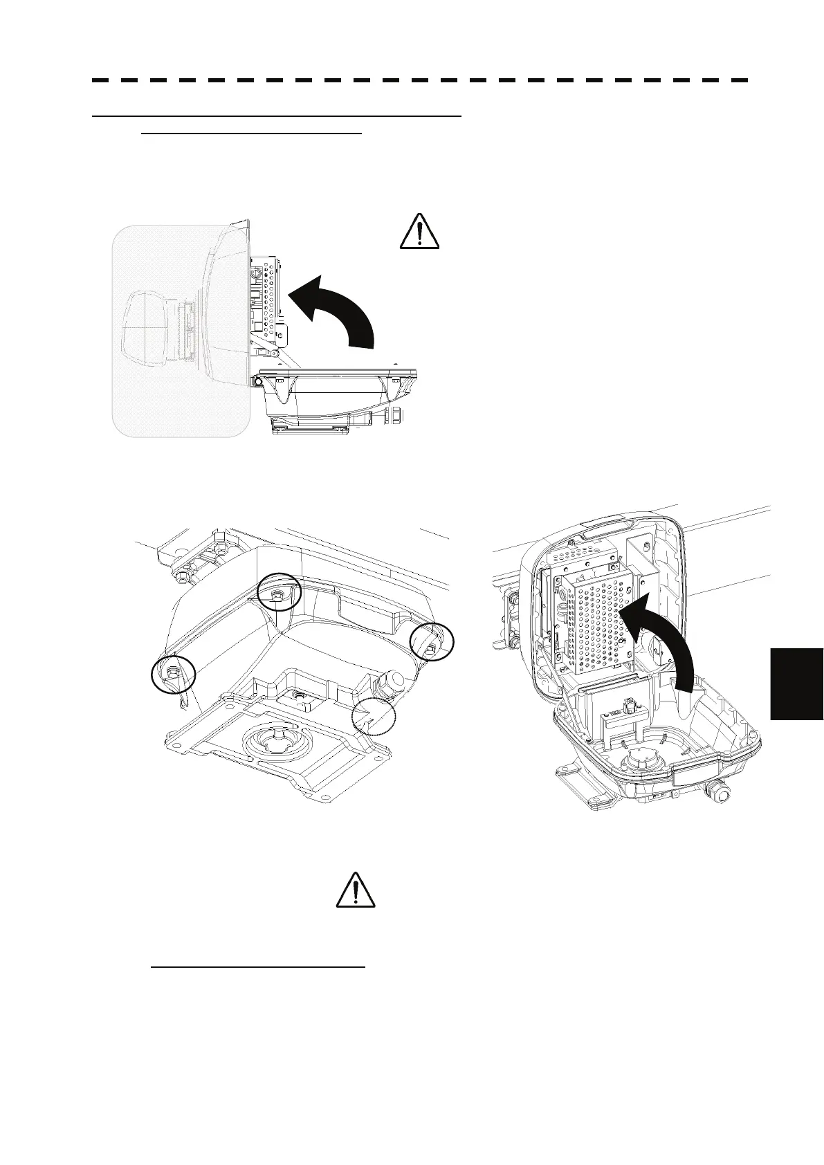
How to replace a 6kW NKE-2063A antenna motor
Step 1: Open the upper housing.
Open or close the scanner unit by turning the upper housing (including the antenna) to the
bow side.
The gray area shown in the figure below must be clear.
Check if you can open or close safely for work.
Be careful with the antenna behavior when
opening or closing.
Be careful with the antenna not to hit the mast
or platform.
Open it slowly. Do not apply too much force to
the stay, otherwise, it may break.
The upper housing is fixed with 4 M8 hexagonal
bolts.
Loosen those hexagonal bolts.(Bolts are falling-out prevention bolts.)
Open the upper housing by rotating upward to the bow side.
Check if the upper housing is stable while opened.
If it is unstable, it will be dangerous while working.
Step 2: Remove the motor unit.
The motor unit is installed in the starboard bow side (starboard lower side when opened) of the
scanner.
Remove the motor cable.
Remove the connectors of the cables connected to the transceiver unit.
The motor is fixed with 4 upset head bolts (M6X45FE) and spring washers (SW6).

 Loading...


