B-18
JMA-7100 Instruction Manual > B.DRAWINGS > B.5 Block Diagram of Scanner Unit
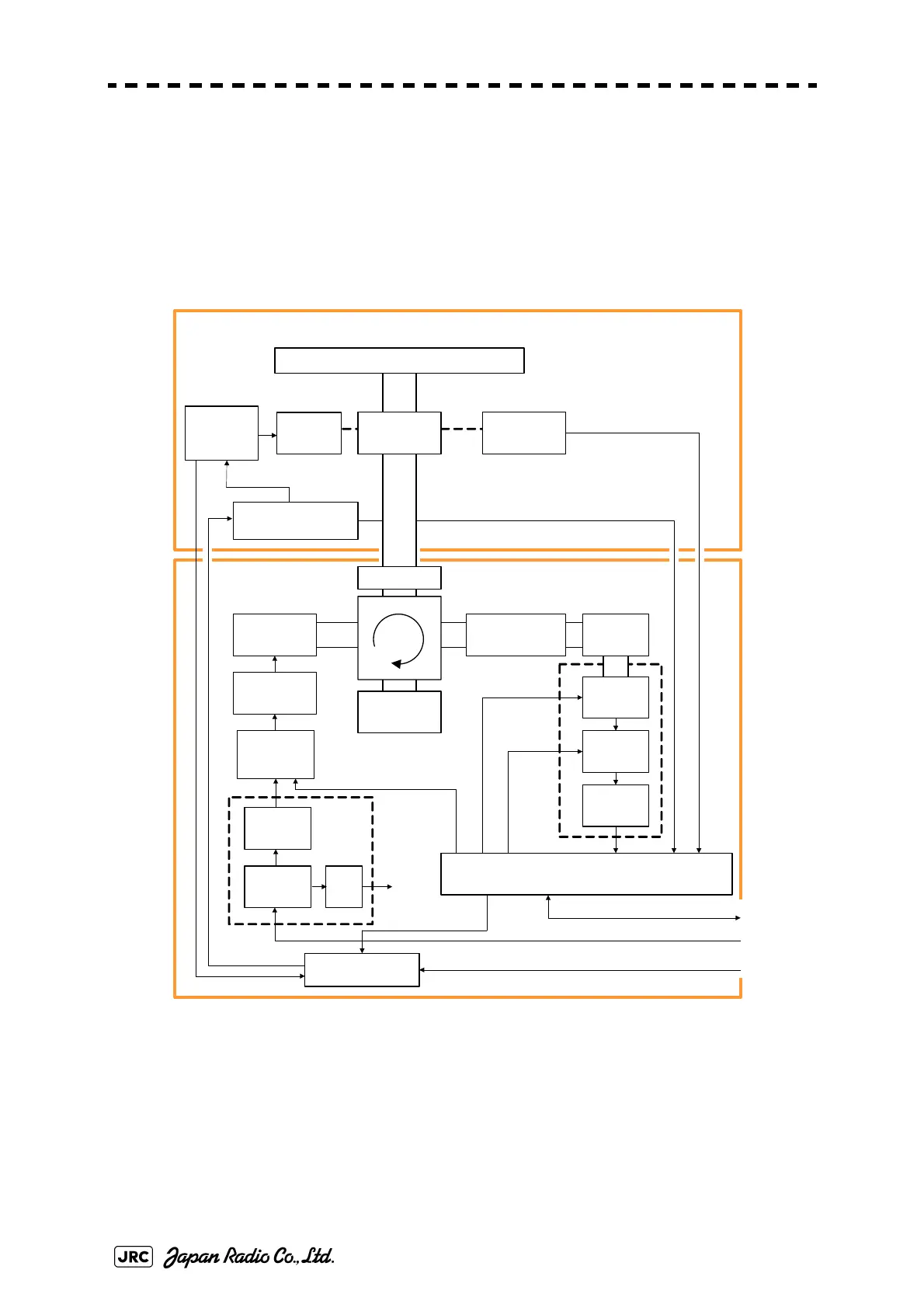
B.5.4 NKE-1129, NTG-3225 / NKE-1139, NTG-3230
Fig B-16: Block Diagram of NKE-1129, NTG-3225 / NKE-1139, NTG-3230
SLOT ANTENNA
ENCODER
MOTOR
B101
SAFETY SWITCH
S101
MAG
V101
PULSE
TRANS
INTERFACE CIRCUIT
PC1101
DIODE LIMITER
/ TRHPL
PIN ATT
(X-band)
RF AMP
IF AMP
VIDEO
AMP
Receiver
Bandwidth
Control
Tune C ontrol
ΦA,ΦB, ΦZ
DUMMY
LOAD
MOTOR
DRIVER
PC1501
AC100-115 / 220 -240 V
50/ 60Hz , 1φ
DC+48V
Serial Com, BP , BZ , VD, TRIG
NKE-1139/NKE-1129 Scanner Unit
NTG-3230/NTG-3225
Transceiver Unit
SWITCHING
CIRCUIT
PC 201
MH
GENERAT OR
PC1001
POWER
SUPPLY
CIRCUIT
RECEIVER
ERROR
MOTOR RELAY
PC1201
Relay Control
AC100 /110 /220 /230 V
50/60Hz,1φ
ROTARY
JOINT
Status
FILTER
AVR
Tx Trigger/Pulse Width
 Loading...