M
matthewramosAug 9, 2025
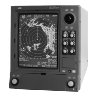
What to do if there is poor contact of connector within JRC Marine Radar unit?
- Kkimberly78Aug 9, 2025
If you suspect a poor contact within a connector of your JRC Marine Radar unit, it is recommended to request assistance from a specialist engineer for repair or further instructions.