Music
INFINITY
Life
02
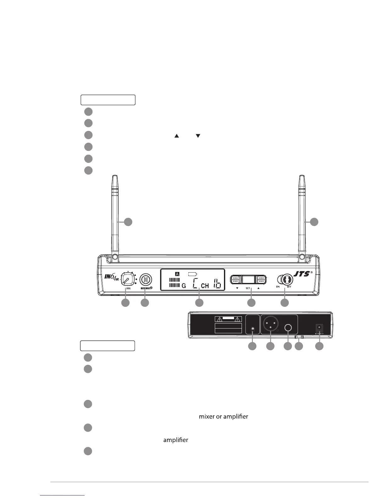
3. Parts Identification
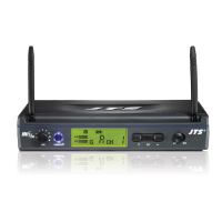
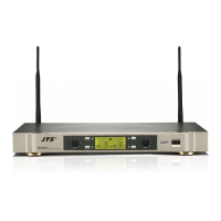
3-1 IN64R
Front panel
Receiving Antennas
Power Switch
Channel Select:
including “ up”, “ down” and “Set” button
LCD Panel
REMOSET Key:
press it to send a desired channel data to a transmitter
Volume Control
Rear panel
Power Supply Jack (12-18V/600mA): for connecting the power supply unit
Strain Relief: for the connection cable of the power supply unit, which lead the cable
around the hook to prevent accidental disconnection of the plug from
the jack.
AF Output (6.3mm jack, balance): for connection to a balance input, e.g. of a
Balanced XLR Output: for connection to the balanced input, e.g. of a mixer or an
Output Level Attenuation(-20dB): to attenuate the balanced output level by 20dB
AF
RF
0dB
-20dB
AF
OUTPUT
OUTPUT
LEVEL
Serial No.:
Freq.Range:
RISK OF ELECTRIC SHOCK
DO NOT OPEN
CAUTION
DCV INPUT
12-18V/200mA
BALANCED BALANCED
1
2
3
4
5
6
7
8
9
10
11
1 1
23456
7891011
 Loading...