05
MIXER
AUDIO OUTPUT
DC INPUT
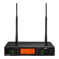
Figure 1
0dB
-20dB
AF
OUTPUT
OUTPUT
LEVEL
Serial No.:
Freq.Range:
CAUTION
DCV INPUT
12-18V/200mA
BALANCED BALANCED
24 7
9
8
10
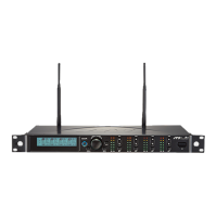
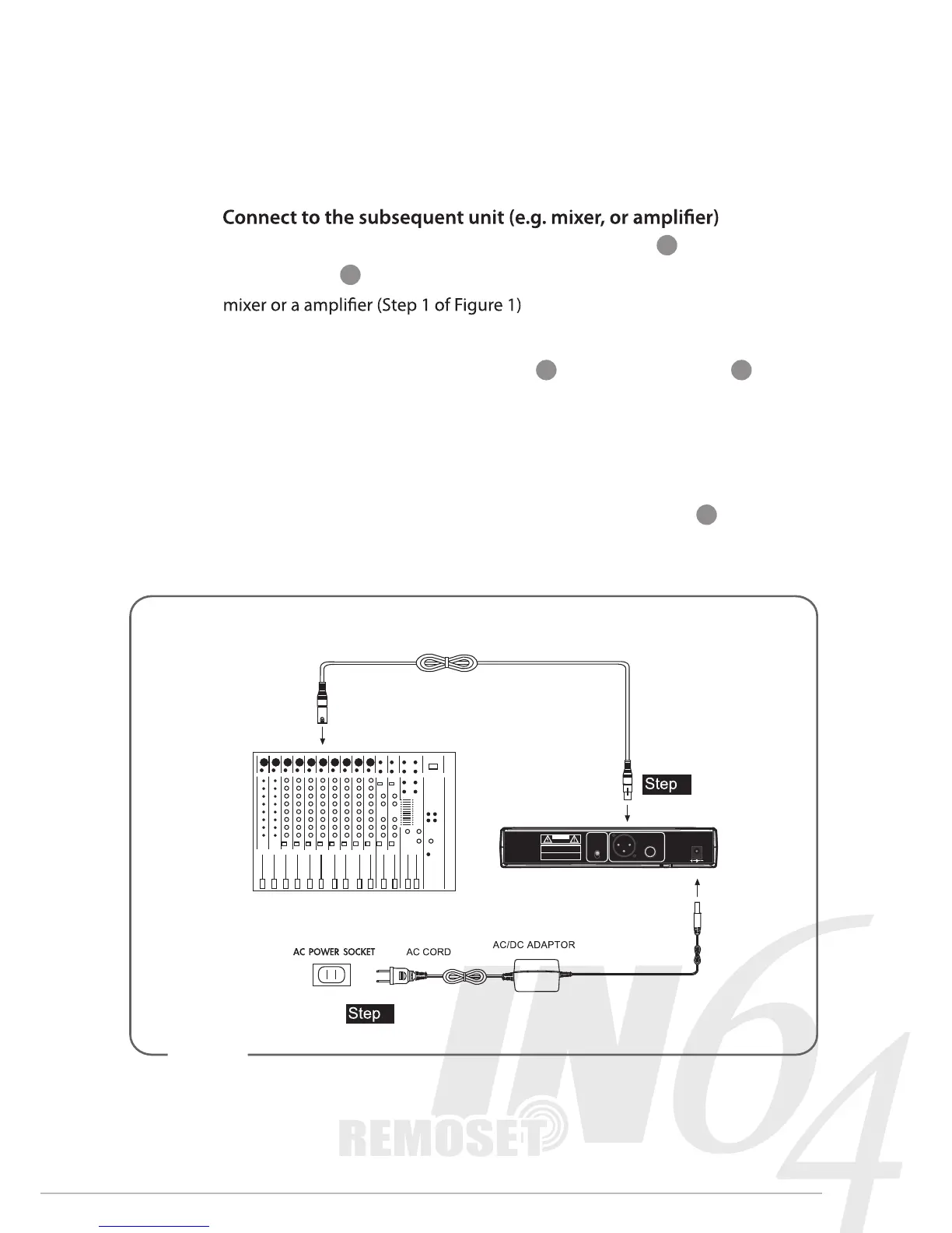
4. Connection
1.
Connect one end of a proper AF cable to the AF Output or Balanced XLR
Output socket , then plug another end to the “MIC IN” input socket of a
2. Connect the power supply unit
Plug in one end of AC/DC adaptor cable to Power Supply Jack in the
rear panel of receiver, and plug another end into an AC outlet
(Step 2 of Figure 1)
Caution
To prevent accidental disconnection of the plug of the power supply unit
from the jack, lead the cable around the hook for strain relief
2
1
 Loading...