– 10 –
Connector No. Destination Terminal No.
CN19 Thread trimming STM 1
A
8.5Ω
2 A
3 B
8.5Ω
4
B
CN20 Controller socket 1 GND
2 Controller
CN21 MotorlterPCB 1 Main motor (+) (29V)
2 Main motor (-)
3 FG
CN22 Power supply relay lead
wire
1 30V
2 30V
3 NC
4 GND
5 GND
CN23 Straight stitch slide plate
sensor PCB
1 Straight stitch slide plate switch
2 GND
CN24 Reserve 1 (Not installed) 2 GND
CN25 Reserve 2 (Not installed) 3 GND
CN26 Reserve 3 (Not installed) 1 5V
3 GND
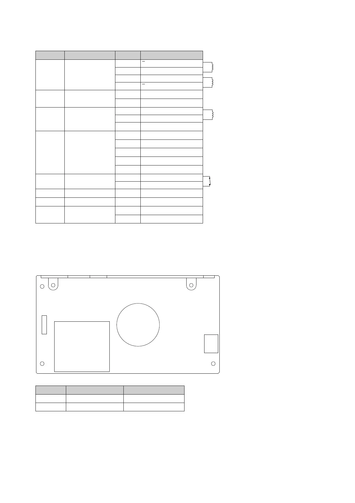
• Power PCB
Connector No. Destination Check
CN1 Power SW AC input
CN2 Power supply relay lead wire 1-2PIN 29V, 4-5PIN GND (FG)
CN1
CN2
 Loading...