Following connectors are prepared when loosening the connector cover
1
xing screws
A
of SC-810 and
opening the cover. Connect the machine head connectors to the positions corresponding to each other so as
to t the devices mounted on the machine head.
WARNING :
• To prevent personal injury caused by abrupt start of the sewing machine, carry out the work after
turning OFF the power switch and a lapse of 5 minutes or more.
• Topreventdamageofdevicecausedbymaloperationandwrongspecications,besuretoconnect
allthecorrespondingconnectorstothespeciedplaces.
• To prevent personal injury caused by maloperation, be sure to lock the connector with lock.
• As for the details of handling respective devices, read carefully the Instruction Manuals supplied
with the devices before handling the devices.
4. Connecting the cords
1
CN30
Motor signal connector
2
CN36
Machine head solenoid connector
3
CN37
Presser foot lifter solenoid connector
4
CN56
Safety switch
5
CN38 CP panel connector
6
CN55 CN55 +24V power
7
CN50 Output connector for optional
AA
2
3
1
4
5
Unused connector
6
7
1
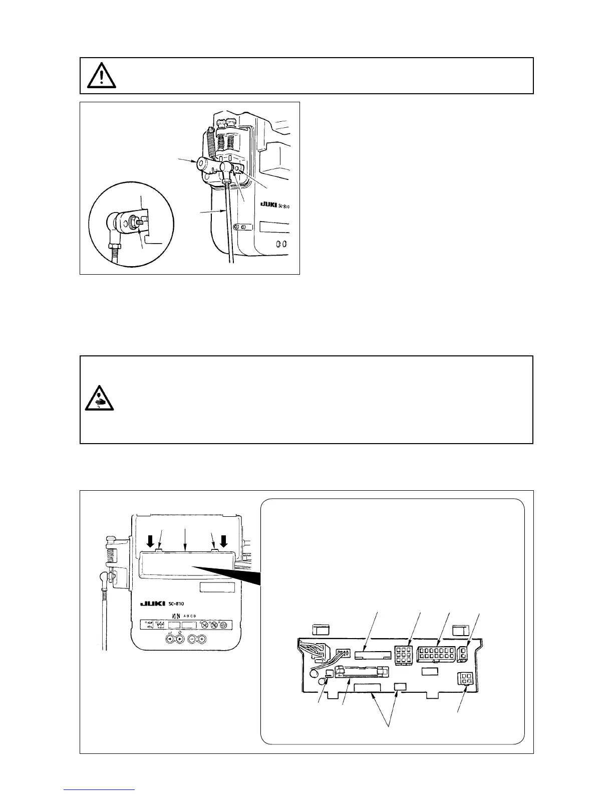
3. Attaching the connecting rod
WARNING :
To protect against possible personal injury due to abrupt start of the machine, be sure to start the
following work after turning the power off and a lapse of 5 minutes or more.
1) Fix connecting rod
1
to installing hole
B
of ped
-
al lever
2
with nut
3
.
2) Installing connecting rod
1
to installing hole
A
will lengthen the pedal depressing stroke, and
the pedal operation at a medium speed will be
easier.
1
2
A
B
3