13
3 Modbus protocol description
3 Modbus protocol description
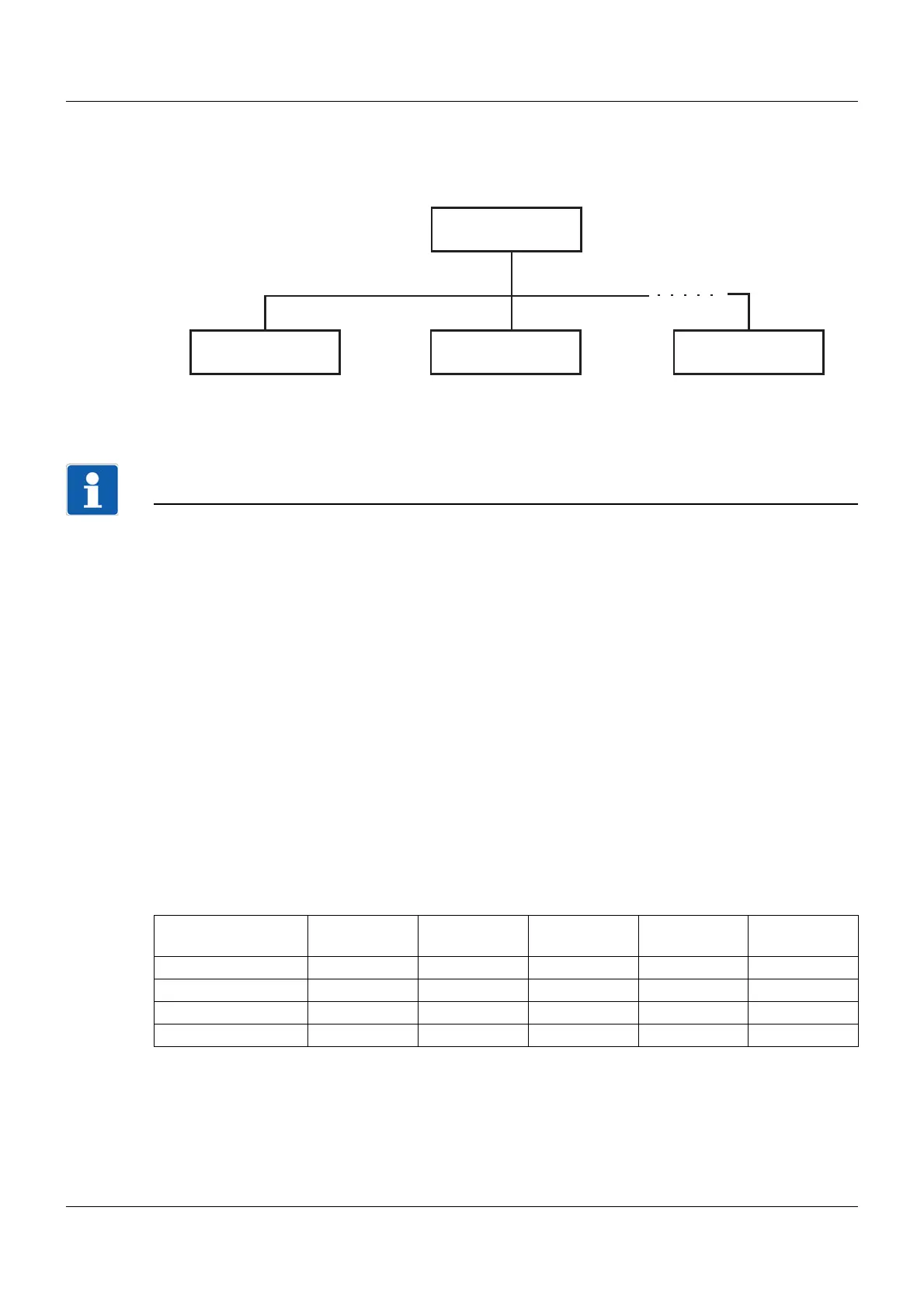
3.1 Master-slave principle
Communication between a master and a slave device with Modbus takes place according to the master/
slave principle in the form of data request/instruction – response.
The master controls the data exchange; the slaves only have a response function. They are identified
by their device address.
NOTE!
This device can only be operated as a Modbus slave.
The Modbus master can read and write different device data, configuration parameters, and device pro-
cess values. Refer to the Modbus address tables for details.
chapter 4 "Modbus addresses", Page 25
3.2 Transmission mode
RS485
RTU mode (Remote Terminal Unit) is used as the transmission mode. The transmission of a character
is therefore performed in binary format with 8 data bits, 1 start bit, 1 or 2 stop bits, and, if necessary, 1
parity bit (see data format). The highest value bit (MSB, most significant bit) is transmitted first.
The ASCII operating mode is not supported.
Ethernet
Via Ethernet, the protocols Modbus-TCP and Modbus-RTU/ASCII via TCP/IP are supported, whereby
the protocol used is automatically recognized. A character is transmitted exclusively with 8 data bits, 1
start bit and 1 stop bit (8-1-no parity; see data format).
Data format
The data format describes the structure of a transmitted character.
Master
Slave 1 Slave 2 Slave n
Data format (con-
figuration)
Start bit Data bits Parity bit Stop bit Number of
bits
8 - 1 - no parity180110
8 - 1 - odd parity181111
8 - 1 - even parity181111
8 - 2 - no parity180211
 Loading...


