EasyManuals Logo

JUMO EM Series User Manual

JUMO EM Series
44 pages
To Next Page IconTo Next Page
To Previous Page IconTo Previous Page
Page #25 background imageLoading...
Page #25 background image
25
5 Installation
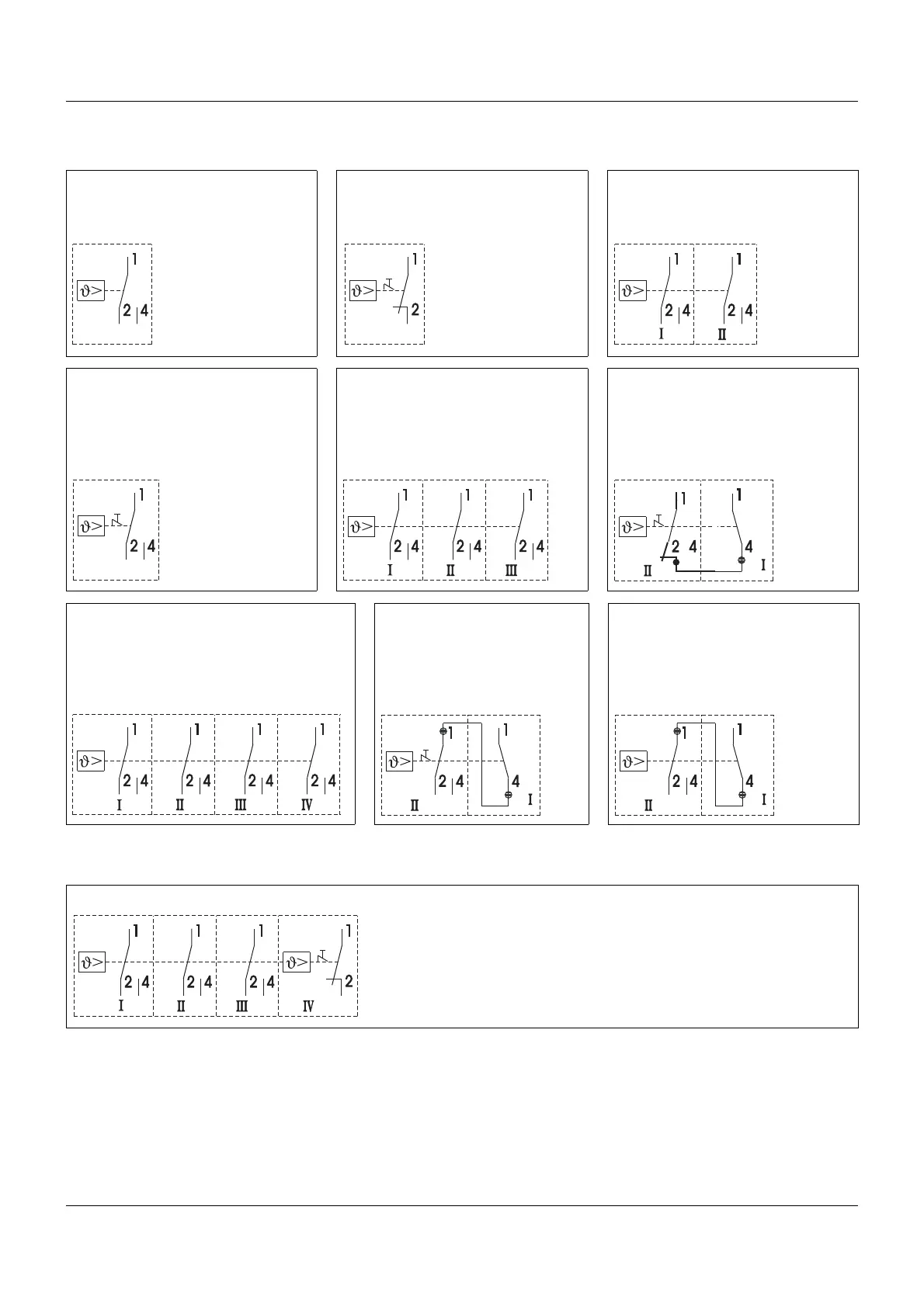
5.3 Connection diagram
Example EMF-1334
EM-1, EM-2, EM-3 EM-4, EM-5 EM-13, EM-23, EM-33
Setpoint: I
Sequence contact: II
EM-4/574, EM-5/574 EMF-133, EMF-233, EMF-333
Setpoint: I
Sequence contact: II, III
EM-40, EM-50
n.c. (break) contact
on measuring system failure
and T < -10 °C: I
Limit value: II
EMF-1333, EMF-2333, EMF-3333
Setpoint: I
Squence contact: II, III, IV
EM-40/574, EM-50/574 EM-20, EM-30
n.c. (break) contact
on measuring system failure
and T < -10 °C: I
Limit value: II
For additional type variants, the connection diagrams are combined appropriately.

Other manuals for JUMO EM Series

Questions and Answers:

Question and Answer IconNeed help?

Do you have a question about the JUMO EM Series and is the answer not in the manual?

JUMO EM Series Specifications

General IconGeneral
Housing MaterialPlastic
Temperature Range-50 to 400°C
DisplayLCD
Power Supply24 V AC/DC
OutputRelay, Analog
InputAnalog
Control ModePID, On/Off

Related product manuals