JUNCTEK
JDS8000 Series User’s Manual
(3) USB Interface
Used to connect the generator to a computer which can control the generator
remotely using PC software or by programming.
(4) DC Power Socket
Positive inside and negative outside, voltage/current specifications:
DC5V±0.5V 3A.
(5) AC Power Socket
The AC power supply specification of this signal generator is 85-264V,
47-63Hz. The maximum input power cannot exceed 30W. The specification of
the fuse is 250V, T3.15A.
(6) Switch
Used to turn the signal generator on or off.
(7) Cooling Holes
Used to dissipate the heat generated inside the instrument.
(8) Chassis Ground
Used to connect with the ground to prevent personal electric shock and ensure
the normal operation of the electrical system.
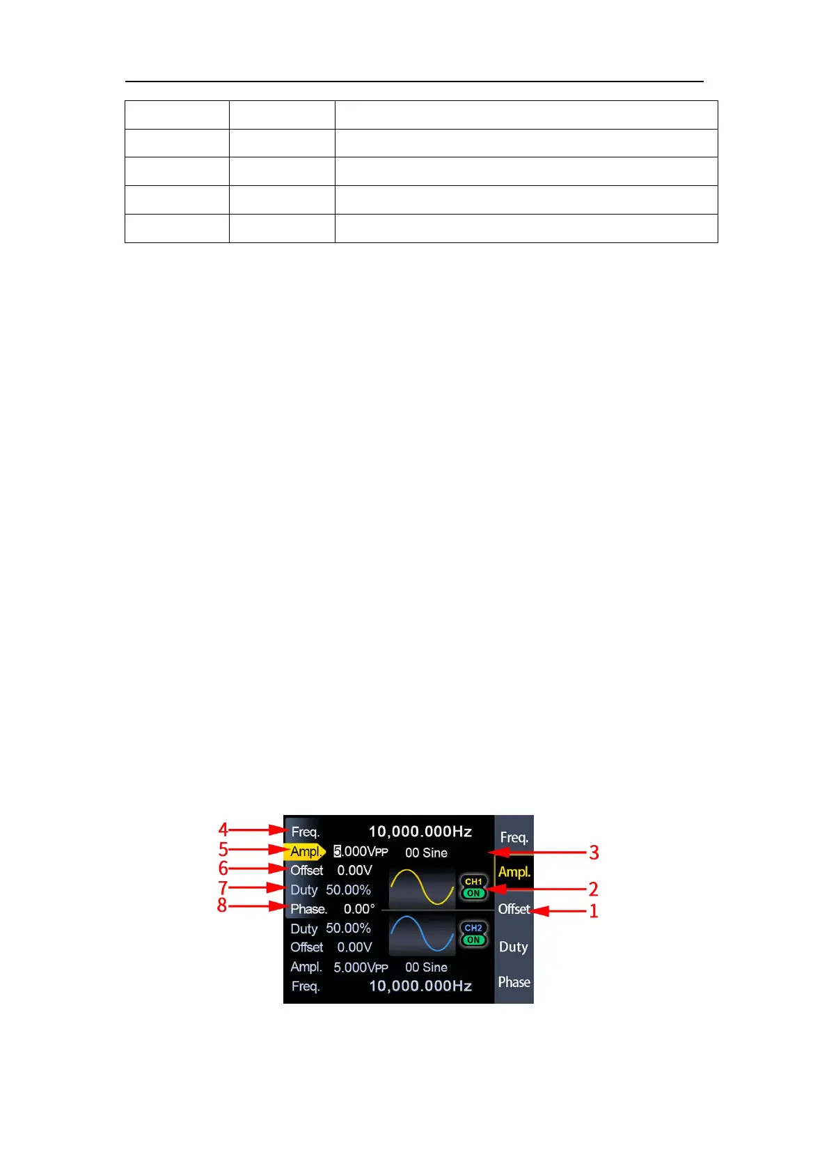
3.Display Interface
Figure 2-3-1 JDS8000 series display interface diagram
Digital signal output interface 2
Serial communication RXD receive data
Serial communication TXD send data
 Loading...