JUNCTEK
JDS8000 Series User’s Manual
The maximum and minimum values of the external input signal voltage can be
calibrated. The minimum voltage calibration corresponds to the starting duty
cycle, and the maximum voltage calibration corresponds to the stop duty cycle.
Voltage control mode
Press soft key
【 】
to make the cursor in the position of voltage control mode
to select linear and logarithmic mode.
Turn on voltage control amplitude
Press the soft key
【
ON
】
, the instrument starts to control the duty cycle by
voltage, and you can observe the change of the duty cycle on the display
interface.
6. Measurement mode parameter settings
Press
【
MEAS
】
,and press
【
Cnt
】
and
【
Meas
】
soft keys in the
measurement mode interface to perform the measurement function and the
counter function.
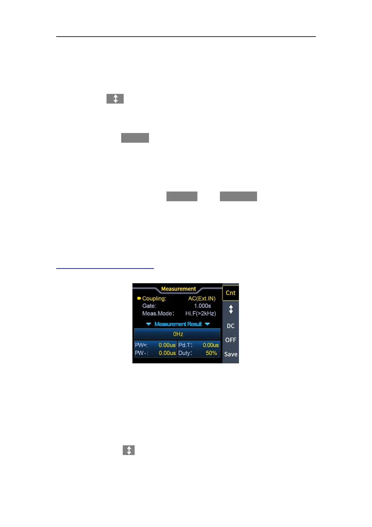
Switching can also be performed by rotating the knob. The measurement
interface is shown in Figure 3-6-1 below.
Measurement functions description video link:
https://youtu.be/XyYnHUjukdI
Figure 3-6-1 measurement interface
(1) Measurement function
The frequency, period, positive pulse width, negative pulse width, duty cycle
and other parameters of the input signal can be measured. The measurement
frequency range is 1Hz-100MHz, the measurement signal amplitude range is
2Vpp-20Vpp, and the input interface is Ext.IN.
Coupling settings
Press the soft key
【 】
to place the cursor at the coupling position, and adjust
the knob to switch the coupling mode between AC (AC) or DC (DC).
 Loading...