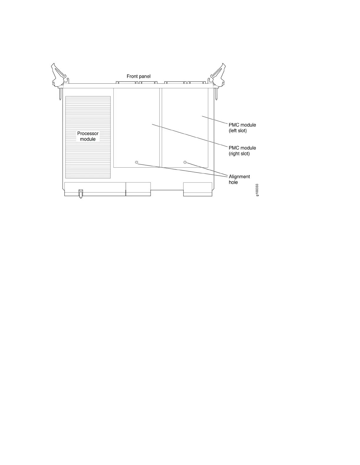
Figure 39: CTP2000 Platforms PMC Location
To install a PMC:
1. Confirm that the device is powered off.
2. Remove the processor module by unscrewing the retaining screws and pushing the extractors outward
while depressing the latching buttons.
3. If a PMC was not previously installed, a shield may have been inserted in the PMC slot of the processor’s
front panel. Remove this shield by gently pushing it out from behind the panel.
4. The PMC has four screws. Two of the screws are secured to standoffs, and two are attached to the
front assembly of the PMC. Remove the two screws secured to the standoff, leaving the standoff
attached to the PMC. Remove the two screws on the front assembly located on the side with the
standoffs. The front assembly should remain attached to the PMC hardware. Keep the screws for
reattachment.
5. Align the PMC with the printed circuit board connectors toward the processor board and with the fiber
connectors inserted through the processor’s front panel. Align the alignment post on the processor
module with the PMC’s alignment hole.
6. Gently press the PMC into the processor module.
100

 Loading...


