Example: Configuring MX Series Router ATM Ethernet Interworking
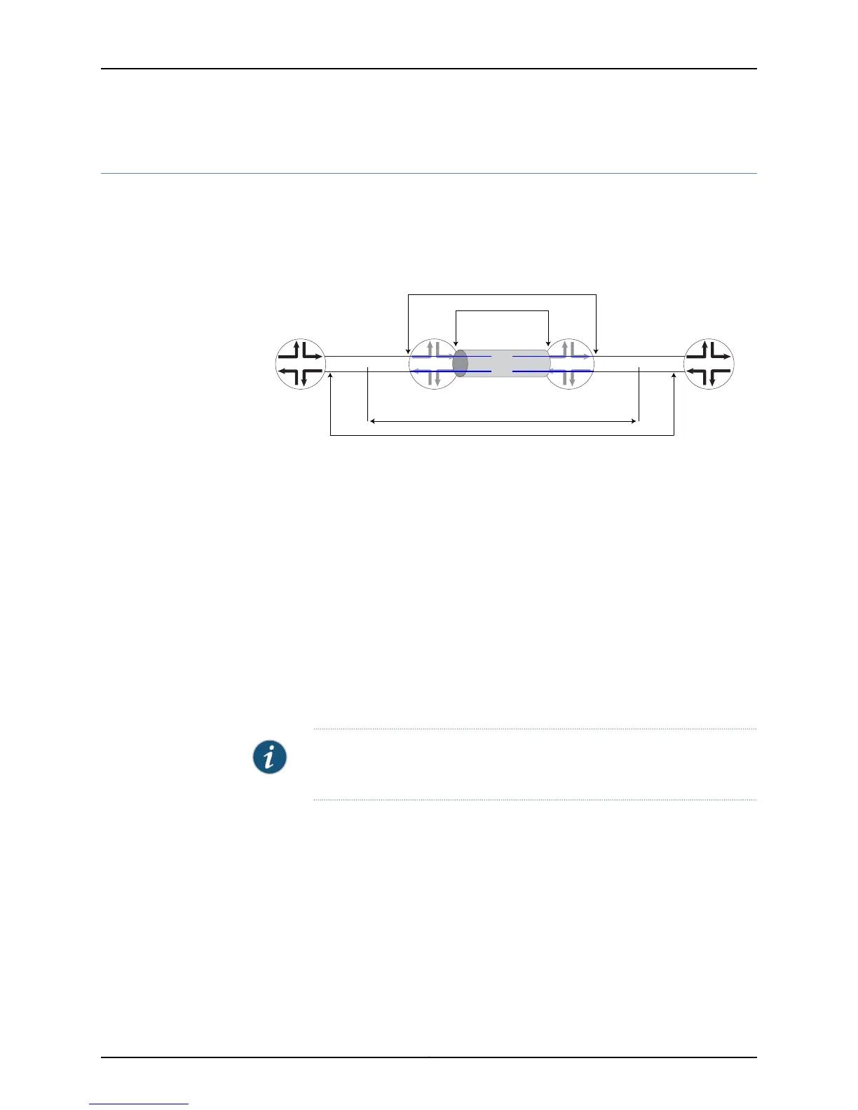
Consider the router topology shown in Figure 13 on page 79. The MX Series router is
configured as the Router PE2 (the provider edge 2 router) in the figure to support the
ATM Ethernet IWF.
Figure 13: ATM Ethernet VLAN Interworking
CE1 CE2
g017428
ATM DSLAM Service Stacked VLAN Service
VPI maps to outer VLAN tag
VCI maps to inner VLAN tag
L2 circuits (if-switch)
I/P backhaul
Provider Edge 1 Provider Edge 2
LSP1
LSP2
Customer Edge 1:
ATM DSLAM
Customer Edge 2:
Ethernet B-RAS
PE1 PE2
The relevant router interfaces are as follows:
•
On Router CE1, the CE1–PE1 interface is at-2/0/0 with IP address 30.1.1.1/24.
•
On Router PE1:
•
The PE1–CE1 interface is at-2/0/1 with no IP address required.
•
The PE1–PE2 interface is ge-5/0/0 with IP address 20.1.1.1/24.
•
On Router PE2:
•
The PE2–CE2 interface is ge-0/2/0 with no IP address required.
•
The PE2–PE1 interface is ge-0/2/8 with IP address 20.1.1.10/24.
•
On Router CE2 interface is ge-0/0/0 with IP address 30.1.1.10/24.
NOTE: The example configurations in this section are not complete
configurations.
Consider the following example MX Series router configurations.
•
Configuring Router PE2 with a Layer 2 Circuit on page 80
•
Configuring Router PE2 with a Layer 2 Circuit over Aggregated Ethernet on page 82
•
Configuring Router PE2 with a Remote Interface Switch on page 85
•
Configuring Router PE2 with a Remote Interface Switch over Aggregated
Ethernet on page 88
79Copyright © 2012, Juniper Networks, Inc.
Chapter 8: MX Series Router in an ATM Ethernet Interworking Function