Related
Documentation
M7i Chassis Description on page 11•
• M7i Midplane Description on page 12
• Maintaining the M7i Routing Engine on page 192
• Removing the PC Card on page 156
• Inserting the PC Card on page 157
Replacing the Console or Auxiliary Cable
If a cable is already connected to the CONSOLE or AUX/MODEM port, follow these steps
to remove it:
1. Turn off the power to the console or auxiliary device.
2. Unscrew the screws that secure the cable connector to the port, using a 2.5-mm
flat-blade screwdriver if necessary.
3. Pull the cable connector straight out of the port.
4. Disconnect the cable from the console or auxiliary device.
To connect the new cable, follow these steps:
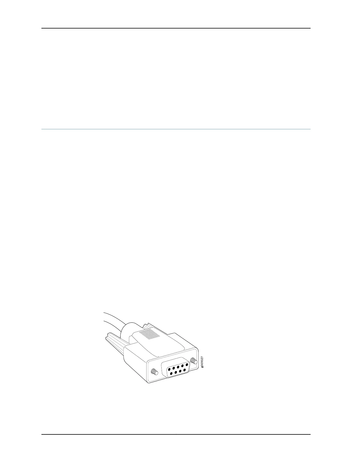
1. Plug the female end of the replacement serial cable into the CONSOLE or AUX/MODEM
port (see “Routing Engine Interface Ports” on page 145).
2. Tighten the screws on the connector.
3. Power on the auxiliary or console device.
Figure 50: Console and Auxiliary Serial Port Connector
Related
Documentation
Fiber-Optic and Network Cable Specifications for the M7i Router on page 91•
• M7i Chassis Description on page 11
Copyright © 2019, Juniper Networks, Inc.148
M7i Multiservice Edge Router Hardware Guide
 Loading...