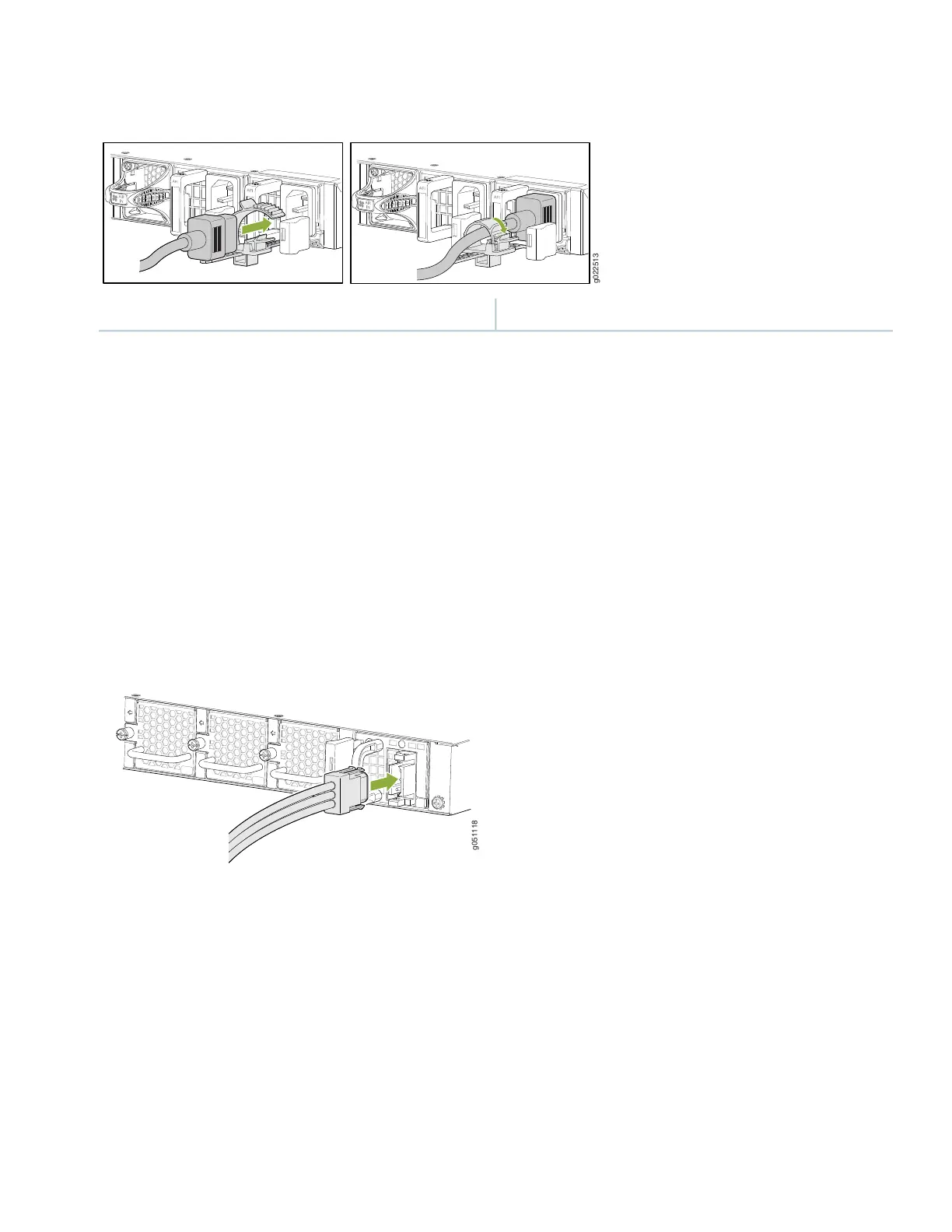
Figure 16: Connecting Power to an AC-Powered QFX5120-48Y Switch
1—Retainer tab loop
To connect power to a DC-powered QFX5120-32C switch:
1. Attach the grounding strap to your bare wrist and to a site ESD point.
2. Ensure that the input circuit breaker is open so that the voltage across the DC power source cable leads is 0 V and
that the cable leads do not become active while you are connecting DC power.
3. Ensure that the power supplies are fully inserted in the chassis.
4. Connect each power supply to the power source by inserting the DC connector of the provided power cable into the
power supply. See Figure 17.
Figure 17: Connecting Power to a DC-Powered QFX5120-32C Switch
5. Connect each power cable to the power sources. Secure power source cables to the power supplies by screwing the
ring lugs attached to the cables to the appropriate terminals.
•
Connect the ring lug of the green-yellow cable to earth ground.
•
Connect the ring lug of the black cable to the negative (–) DC power source.
•
Connect the ring lug of the red cable to the positive (+) DC power source.
The QFX5120-32C is designed to operate with a DC power supply that has a single, non-redundant, feed input. For
source redundancy, two DC power supplies must be installed in QFX5200-32C; connect source (A) to one power
supply and connect source (B) to the second power supply. This configuration provides the commonly deployed A/B
feed redundancy for the system.
11
 Loading...


