1-6 (No.XA020)
SECTION 3
DISASSEMBLY
3.1 Main body section
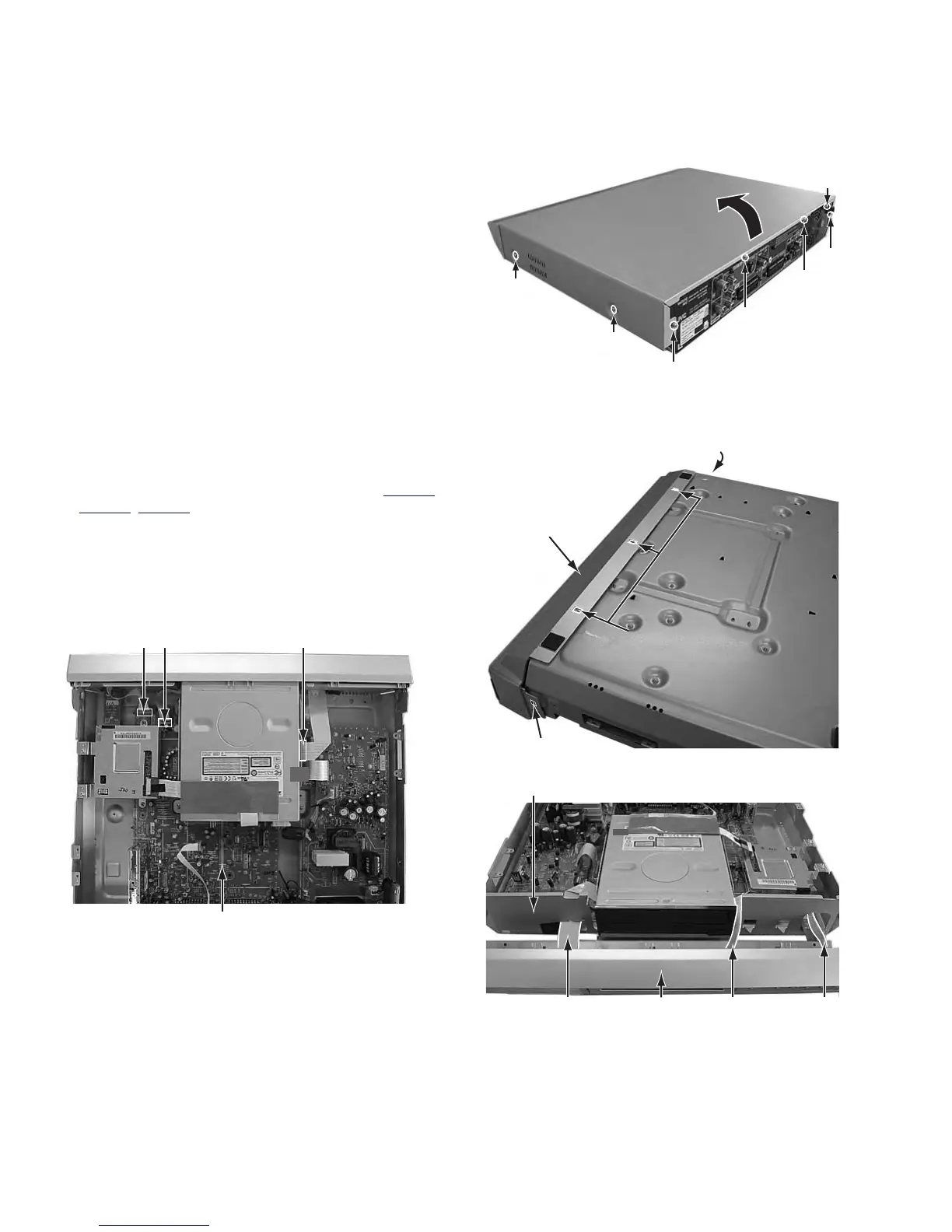
3.1.1 Remove the top cover (See figure 1)
(1) Remove the four screws A attaching the top cover on both
sides of the main body.
(2) Remove the five screws B attaching the top cover on the
back of the main body.
(3) Raise the both sides and lower part of the rear of the top
cover, with opening them slightly in an outward direction.
And the top cover will be removed.
Fig.1
3.1.2 Remove the front panel assembly (See figure 2, figure 3, and figure 4)
• Prior to performing the following procedure, remove the top
cover.
• There is no need to remove the mechanism assembly.
(1) Disconnect the card wires from connector CN3001
,
CN3002, CN4001 on the main board.
(2) Hooks a and b are removed respectively, and the front
panel assembly is removed.
NOTE:
In case of attach a front panel assembly, please let a
card wire pass in the hole in the front part of a chassis,
respectively, and connect.
Fig.2
Fig.3
Fig.4
B
B
A x 2
TOP COVER
TOP COVER
B
A x 2
B
B
CN3002CN4001 CN3001
Main board
Hook a
Hook a
Hook b
Front panel
assembly
Front panel
assembly
Card wireCard wire
Chassis of front part
Card wire