(No.XA020)1-7
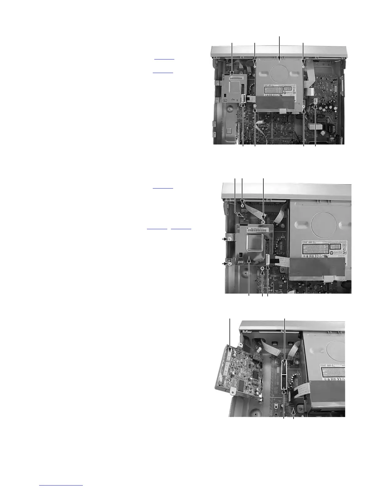
3.1.3 Remove the mechanism assembly (See figure 5)
• Prior to performing the following procedure, remove the top
cover.
• There is no need to remove the front panel assembly.
(1) Disconnect the socket wire from connector CN5303
on the
power supply board.
(2) Disconnect the card wire from connector CN2201
on the
module board.
(3) Remove the four screws C attaching the mechanism as-
sembly.
Fig.5
3.1.4 Remove the module board (See figure 6, figure 7)
• Prior to performing the following procedure, remove the top
cover.
(1) Disconnect the card wire from connector CN2201
on the
module board.
(2) Remove the four screws D and E attaching the module
board.
(3) Remove the one screw F attaching the DV terminal board.
(4) Lift the module board up, and remove it. Then, the module
board is removed from the connectors CN4101
, CN4102
on the main board. In attaching the module board, insert
the connector on the module board in these connectors se-
curely.
Fig.6
Fig.7
C
Mechanism assembly
C
CN2201 C C CN5303
Module board
EF
D
D
CN2201
EModule board
DV terminal
board
Module board
Main boardCN4101
CN4102