1-8 (No.XA020)
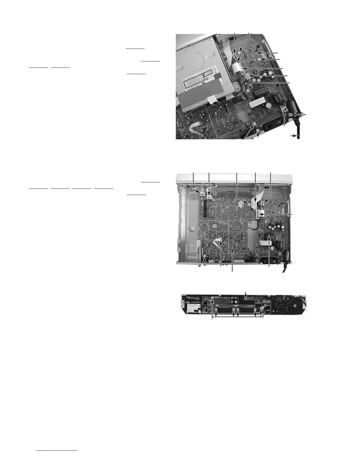
3.1.5 Remove the power supply board (See figure 8)
• Prior to performing the following procedure, remove the top
cover.
(1) Disconnect the card wire from connector CN5301 on the
power supply board.
(2) Disconnect the socket wire from connector CN5302
,
CN5303
, CN5305 on the power supply board.
(3) Disconnect the power cord from connector CN5001 on the
power supply board.
(4) Remove the two screws G attaching the power supply
board.
(5) Four fasteners are removed.
Fig.8
3.1.6 Remove the main board (See figure 9, figure 10)
• Prior to performing the following procedure, remove the top
cover, mechanism assembly, module board.
(1) Disconnect the card wire from connector CN3001
,
CN3002, CN4001, CN5101, CN7301 on the main board
(2) Disconnect the socket wire from connector CN5302 on the
power supply board.
(3) Remove the two screws H attaching the main board.
(4) Remove the seven screws I attaching the rear panel with
main board.
Fig.9
Fig.10
Power supply
board
CN5001
CN5305
G
G
CN5303
Power cord
Fastener
Fastener
CN5301
Fastener
CN5302
Power supply board
CN5302CN3001H
CN5101
CN3002CN4001
Main board
H CN7301
I
Rear panel