(No. 52152) 1-45
HIGH-VOLTAGE ADJUSTMENT
Measuring Instruments Signal generator (All-black signal)
High-voltage voltmeter
Card (Slot) Component/RGB Input Card (Slot 1)
Test Points Anode of CRT
Adjustment Points VR502 (High-Voltage VR) [S. CORRECTION PWB]
Note: Perform the following adjustments after completing the Screen Voltage Coarse adjustment and X-Ray Protector
adjustment.
(1) Turn the VR502 fully clockwise.
(2) Set the CONTRAST and BRIGHT potentiometers on the front panel to the fully clockwise positions.
(3) Connect the high-voltage voltmeter to the anode of the CRT and turn the unit ON.
(4) Apply the 1080/60i all-black signal to INPUT A (Terminal Y on the Component/RGB Input Card).
(5) If the raster is visible, adjust the BRIGHT potentiometer on the front panel to turn the screen all black.
(6) Turn the VR502 slowly counterclockwise until the value of the high voltage is 25 kV ± 0.2 kV.
(7) Apply adhesive for fixing the VR502 in the adjusted position.
(8) Set the CONTRAST and BRIGHT potentiometers on the front panel to the center click positions.
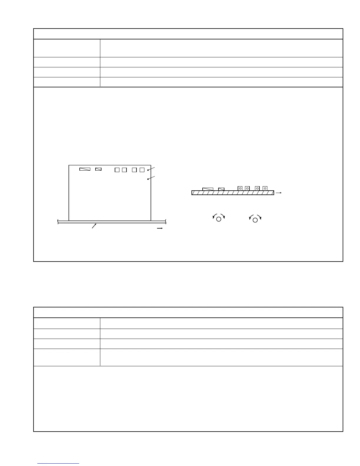
4.10.4 HIGH-VOLTAGE ADJUSTMENT
S. CORRECTION PWB
MAIN PWB
Front side
TP-XR
TP-G
Front side
(Min) (Max)
(Min)(Max)
VR505 [CONV_V]
VR504 [CONV_H]
VR502 [H.VOLTAGE]
VR501 [X-RAY]
CN0RD
CN00R
(Top surface view of S. CORRECTION PWB)
VR505
VR504
VR502
VR501
CN0RD
CN00R
VR502
VR501
FOCUS ADJUSTMENT
Measur Instruments Signal generator (Crosshatch signal)
Card (Slot) Component/RGB Input Card (Slot 1)
Test Points
Adjustment Points FOCUS VR1 [Top potentiometer on high-voltage transformer]
FOCUS VR2 [Middle potentiometer on high-voltage transformer]
Note: Perform the following adjustments after completing the Screen Voltage Coarse adjustment , X-Ray Protector and
High-Voltage adjustments.
(1) Apply the 1080/60i crosshatch signal to INPUT A (Terminal Y on the Component/RGB Input Card).
(2) Set the CONTRAST and BRIGHT potentiometers on the front panel to the center click positions.
(3) Adjust the FOCUS VR1 and VR2 so that the horizontal and vertical lines in the image are clearly visible.
4.10.5 FOCUS ADJUSTMENT
 Loading...