(No. 52152) 1-53
CHROMA/PHASE ADJUSTMENTS (NTSC)
Measuring Instruments Signal generator (Color bar signal)
Oscilloscope
Card (Slot) NTSC/PAL Video Input Card (Slot 2)
Test Points TP-47B [CRT SOCKET PWB]
TP-GND [CRT SOCKET PWB]
Adjustment Points S*03 (Chroma), S*04 (Phase) [Service Menu]
Notes:
• Ensure that the output waveforms from the NTSC/PAL
Video Input Cards are normal before proceeding to the
following adjustments.
• Perform the following adjustments after completing
the 1080/60i signal Chroma/Phase Adjustments.
• Set the CHROMA and PHASE data in the Setup Menu
to “00”.
• The SR value (see the description of the Component
Signal Chroma/Phase Adjustments) becomes the
reference value for the following adjustments. When
this data is changed, it is required to re-adjust the data
of all of the adjustment signals (Component, NTSC and
PAL).
When re-adjusting the 1080/60i signal, use the SI. (For
the adjustment of the 1080/60i signal, use the
Component/RGB Input Card.)
(1) Apply the NTSC 75% color bar signal to INPUT C
(Terminal VIDEO1 on the NTSC/PAL Video Input Card).
(2) Set the CHROMA and PHASE potentiometers on the front
panel to the center click positions.
(3) Connect the oscilloscope across TP-47B and TP-GND.
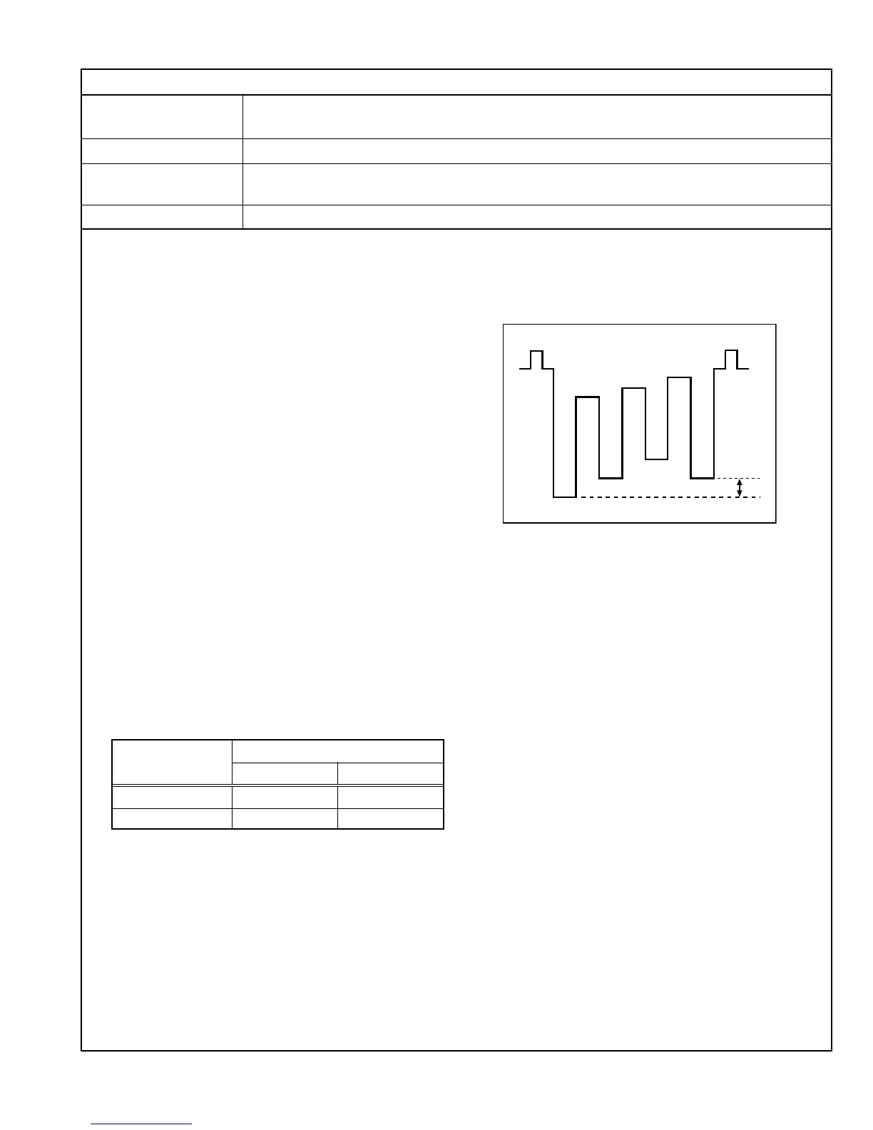
(4) Adjust SA03 in the Service Menu to set the level difference
between waveforms 1 and 4 in the figure on the right to 0
V ± 2 V.
(5) Adjust SA04 to set the level difference between 1 and 3
to 0 V ± 2 V.
(6) Apply the NTSC 75% color bar signal to INPUT D
(Terminal Y/C on the NTSC/PAL Video Input Card) and
perform the adjustments in steps 2 to 5 above. See Table
6 for the adjustment data.
Table 6
Adjustment
Adjustment Data
Signal
Chroma Phase
NTSC (VIDEO) SA03 SA04
NTSC (Y/C) SB03 SB04
4
3
2
1
 Loading...