K D-A
77
A/B/C/E/
J/U
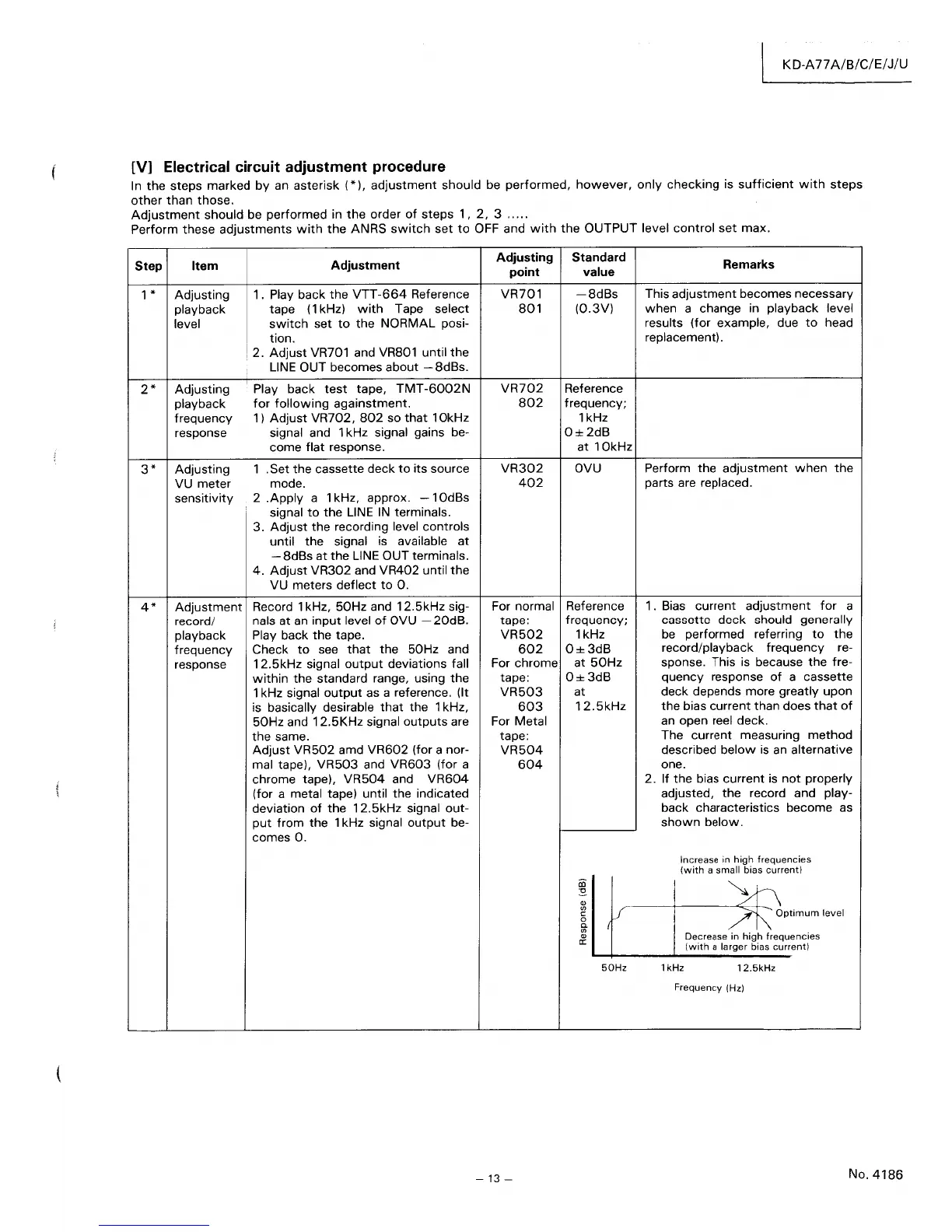
[V]
Electrical
circuit
adjustment
procedure
In
the
steps marked
by
an asterisk
(*),
adjustment
should be
performed,
however,
only
checking
is
sufficient
with
steps
other
than
those.
Adjustment
should be
performed
in
the
order
of
steps
1,
2,
3
.....
Perform these
adjustments
with
the
ANRS
switch
set
to
OFF and
with
the
OUTPUT
level
control
set
max.
Step
Item
1 * Adjusting
2*
3*
4*
playback
level
Adjusting
playback
frequency
response
Adjusting
VU
meter
sensitivity
Adjustment
record/
playback
frequency
response
Adjustment
1. Play back
the
VTT-664
Reference
tape
(1
kHz)
with
Tape select
switch
set
to
the
NORMAL posi-
tion.
2.
Adjust
VR701 and VR801 until
the
LINE
OUT becomes about - 8dBs.
Play back
test
tape,
TMT-6002N
for
following
againstment.
1)
Adjust
VR702,
802
so
that
10kHz
signal and 1 kHz signal gains be-
come
flat
response.
1 . Set
the
cassette deck
to
its source
mode.
2
.Apply
a 1 kHz, approx.
-10dBs
signal
to
the
LINE
IN
terminals.
3.
Adjust
the
recording level controls
until
the
signal is available
at
-8dBs
at
the
LINE OUT terminals.
4.
Adjust
VR302
and VR402 until
the
VU meters
deflect
to
O.
Record 1 kHz,
50Hz
and
12.5kHz
sig-
nals at an
input
level
of
OVU -
20dB.
Play back
the
tape.
Check
to
see
that
the 50Hz and
12.5kHz
signal
output
deviations fall
within
the
standard range, using
the
1 kHz signal
output
as a reference. (It
is basically desirable
that
the 1 kHz,
50Hz
and
12.5KHz
signal
outputs
are
the
same.
Adjust
VR502
amd
VR602
(for a nor-
mal tape),
VR503
and
VR603
(for a
chrome tape),
VR504
and
VR604
(for a metal tape) until the indicated
deviation
of
the
12.5kHz
signal
out-
put
from
the 1 kHz signal
output
be-
comes
O.
Adjusting
point
VR701
801
VR702
802
VR302
402
For normal
tape:
VR502
602
For chrome
tape:
VR503
603
For Metal
tape:
VR504
604
-13
-
Standard
value
-8dBs
(0.3V)
Reference
frequency;
1kHz
0±2dB
at
10kHz
OVU
Reference
frequency;
1kHz
0±3dB
at
50Hz
0±3dB
at
12.5kHz
Ol
:s
Q)
<n
J
c:
0
C.
<n
Q)
er:
50Hz
Remarks
This
adjustment
becomes necessary
when
a change in playback level
results (for example, due
to
head
replacement) .
Perform
the
adjustment
when
the
parts are replaced.
1. Bias current
adjustment
for
a
cassette
deck
should generally
be
performed referring
to
the
record/playback frequency re-
sponse. This is because
the
fre-
quency
response
of
a cassette
deck depends more greatly
upon
the
bias
current
than does
that
of
an open reel deck.
The current measuring
method
described
below
is
an alternative
one.
2. If
the
bias current
is
not
properly
adjusted,
the
record and play-
back characteristics become as
shown
below.
Increase in
high
frequencies
Iwith
a small bias current)
>t\
/1\'
Optimum
level
Decrease in
high
frequencies
Iwith
a larger bias current)
1 kHz
12.5kHz
Frequency
1Hz)
No.4186