KD-A77
A!B!C!E!J!U
Step
Adjustment
8. Check
to
see
if
the
test
point
output
difference
between
that
with
ANRS
switch
set
to
ON
and
that
set
to
OFF is
less than
±
O.
5dB,
with
the
input
a 1 kHz,
-1
OdBs signal. (its signal adjust
to
20dB
with
an attenuator.)
9. Set ANRS
switch
to
SUPER
from
OFF
when
input
10kHz
signal
to
LINE IN. Check LINE OUT level so
that
it
become
from
-
5.5dBs
to
-11.
5dBs ± 1 dB.
(Super
ANRS
circuit
for
playback mode)
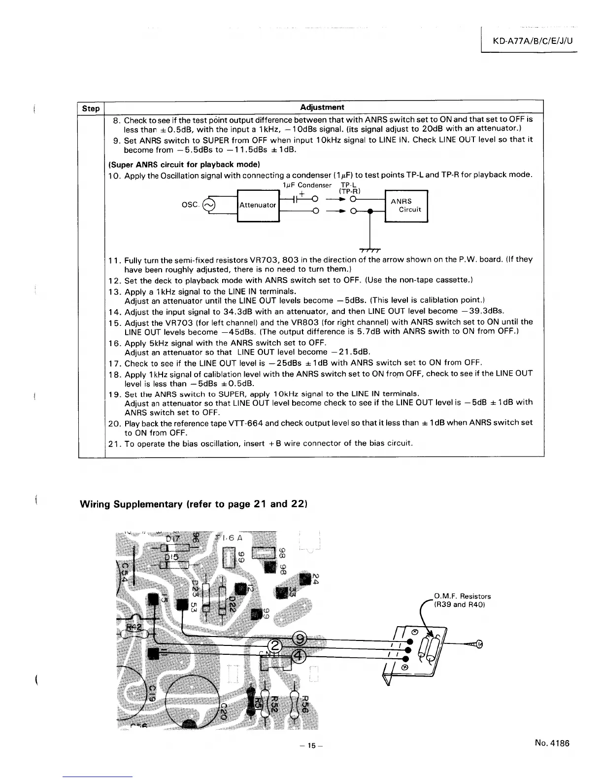
10.
Apply the Oscillation signal
with
connecting a condenser
(1
JLF)
to
test
points
TP-L and TP-R
for
playback mode.
I
~
C:ndenser
(~~~~)
OSC
8L-_---iAttenuator
I
~
=
~~:=::=~
AN~r~uit
7'7
'TT
11.
Fully turn the semi-fixed resistors
VR703,
803
in
the
direction
of
the
arrow
shown
on
the
P.W. board. (If
they
have been roughly adjusted, there is no need
to
turn
them.)
12.
Set the deck
to
playback mode
with
ANRS
switch
set
to
OFF. (Use
the
non-tape cassette.)
13.
Apply a 1 kHz signal
to
the LINE
IN
terminals.
Adjust
an
attenuator
until
the
LINE OUT levels become - 5dBs. (This level is caliblation point.)
14.
Adjust
the
input
signal
to
34.3dB
with
an
attenuator,
and then LINE OUT level become
-39.3dBs.
15.
Adjust
the
VR703
(for
left
channel) and
the
VR803
(for right channel)
with
ANRS
switch
set
to
ON
until
the
LINE
OUT levels become
-45dBs.
(The
output
difference is
5.7dB
with
ANRS
swith
to
ON
from OFF.)
16.
Apply
5kHz signal
with
the ANRS
switch
set
to
OFF.
Adjust
an
attenuator
so
that
LINE OUT level become -
21.
5dB.
1 7. Check
to
see
if
the
LINE OUT level is -
25dBs
± 1 dB
with
ANRS
switch
set
to
ON
from
OFF.
18.
Apply
1 kHz signal
of
caliblation level
with
the
ANRS
switch
set
to
ON
fro,m OFF,
check
to
see
if
the
LINE OUT
level is less than - 5dBs
±
O.
5dB.
19.
Set the ANRS
switch
to
SUPER,
apply
10kHz
signal
to
the
LINE
IN
terminals.
Adjust
an
attenuator
so
that
LINE OUT level become check
to
see
if
the LINE OUT level is - 5dB ± 1 dB
with
ANRS
switch
set
to
OFF.
20.
Play back the reference tape
VTT-664
and
check
output
level so
that
it
less than ± 1 dB
when
ANRS
switch
set
to
ON
from
OFF.
21.
To operate the bias oscillation, insert + B
wire
connector
of
the
bias circuit.
Wiring Supplementary (refer to page
21
and
22)
-15-
O.M.F. Resistors
(R39 and R40)
No.4186