2
• The fuse blows.
]
Are the red and black leads connected correctly?
• Power cannot be turned on.
]
Is the yellow lead connected?
• No sound from the speakers.
]
Is the speaker output lead short-circuited?
• “PROTECT” appears on the display and no operation can be done.
]
Is the speaker output lead
short-circuited or touches the chassis of the car/head unit? ; Have you reset your unit?
• Sound is distorted.
]
Is the speaker output lead grounded? ; Are the “–” terminals of L and R speakers
grounded in common?
• Noise interfere with sounds.
]
Is the rear ground terminal connected to the car’s chassis using shorter
and thicker cords?
• This unit becomes hot.
]
Is the speaker output lead grounded? ; Are the “–” terminals of L and R
speakers grounded in common?
• This unit does not work at all.
]
Have you reset your unit?
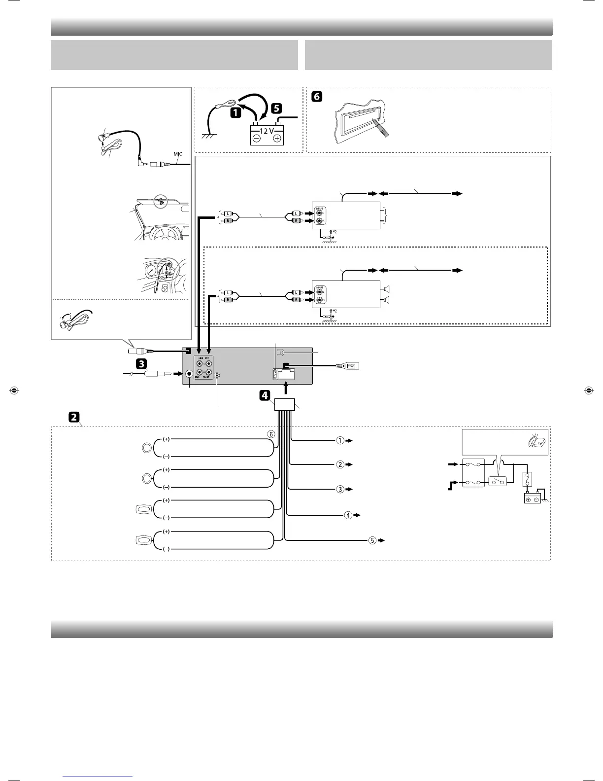
TROUBLESHOOTING /
Black /
Fuse block /
Ignition switch /
Blue (white stripe) /
(
)
Red /
Yellow /
*
3
To the metallic body or chassis of the car /
To an accessory terminal /
To a live terminal (constant 12 V) /
(
12 V)
To the automatic antenna if any (250 mA max.) /
( 250 mA)
White /
White (black stripe) /
(
)
Gray /
Gray (black stripe) /
(
)
Green /
Green (black stripe) /
(
)
Purple /
Purple (black stripe) /
(
)
Signal cord /
*
1
Signal cord /
*
1
Y-connector /
Y *
1
Y-connector /
Y *
1
Remote lead /
Remote lead /
To the blue (white stripe) lead
of the unit /
(
)
To the blue (white stripe) lead
of the unit /
(
)
Rear speakers or subwoofer (Make the <L/O MODE>
setting accordingly, see page 24 of the INSTRUCTIONS.) /
(
<L/O MODE> 24
)
Front speakers /
Rear ground terminal /
15 A fuse /
15 A
Antenna input /
*
1
Not supplied for this unit.
*
2
Firmly attach the ground wire to the metallic body or to the chassis of the car—to the place uncoated
with paint.
*
3
Before checking the operation of this unit prior to installation, this lead must be connected; otherwise,
the power cannot be turned on.
Front speaker (left) /
()
Front speaker (right) /
()
Rear speaker (left) /
()
Rear speaker (right) /
()
ELECTRICAL CONNECTIONS /
Reset the unit. /
JVC Amplifier /
JVC
JVC Amplifier /
JVC
Connecting the external amplifier or subwoofer /
To the remote lead of other equipment (200 mA max.) /
( 200 mA)
Blue
/
*
1
*
2
—
*
3
•
]
?
•
]
?
•
]
?
• “PROTECT”
]
/
? ;
?
•
]
? ;
“–” L () R ()
?
•
]
?
•
]
? ;
“–” L () R ()
?
•
]
?
IMPORTANT: A custom wiring harness (separately purchased) which is suitable for your car is
recommanded for connection between the unit and your car.
• Consult your JVC car audio dealer or a company supplying kits for details.
:
(
)
• JVC
Steering wheel remote input /
H Microphone clip /
Adjust the microphone angle /
Secure the microphone cord
using cord cramps *
1
if necessary. /
*
1
H Microphone clip /
G Microphone /
– – – – – – – – – – or / – – – – – – – – – –
MIC (microphone input
terminal /
)
Connecting the microphone unit /
E Power cord /
USB cable (approx. 1.2 m) / USB ( 1.2 .)
 Loading...