1-10 (No.MA089)
3.1.9 Removing the cassette mechanism assembly
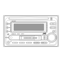
(See Fig.13)
• Prior to performing the following procedure, remove the front
panel assembly, rear bracket, heat sink, bottom chassis as-
sembly, changer control board and mecha control board.
From the bottom side of the bottom chassis assembly, remove
the four screws M attaching the cassette mechanism assembly
to the bottom chassis assembly.
Fig.13
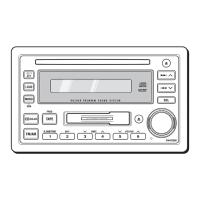
3.1.10 Removing the LCD board
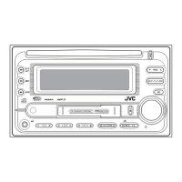
(See Fig.14)
• Prior to performing the following procedures, remove the front
panel assembly.
(1) From the inside of front panel assembly, remove the twelve
screws N attaching the LCD board and take out the LCD
board.
(2) From the reverse side of LCD board, remove the solders
from the soldered sections h attaching the wires.
Fig.14
3.1.11 Removing the switch board
(See Fig.15)
• Prior to performing the following procedures, remove the front
panel assembly.
(1) From the inside of front panel assembly, remove the five
screws P attaching the switch board.
(2) Release the claws i attaching the switch board in the direc-
tion of the arrow and take out the switch board.
(3) From the reverse side of switch board, remove the solders
from the soldered sections j attaching the wires.
Fig.15
M
Cassette mechanism assembly
Bottom chassis assembly
M
Front panel assembly
LCD board
h
N
N
NN
P
Front panel assembly
Switch board
P
i
j
w
w
w
.
x
i
a
o
y
u
1
6
3
.
c
o
m
Q
Q
3
7
6
3
1
5
1
5
0
9
9
2
8
9
4
2
9
8
T
E
L
1
3
9
4
2
2
9
6
5
1
3
9
9
2
8
9
4
2
9
8
0
5
1
5
1
3
6
7
3
Q
Q
TEL 13942296513 QQ 376315150 892498299
TEL 13942296513 QQ 376315150 892498299
http://www.xiaoyu163.com
http://www.xiaoyu163.com
 Loading...