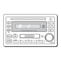
(No.MA089)1-13
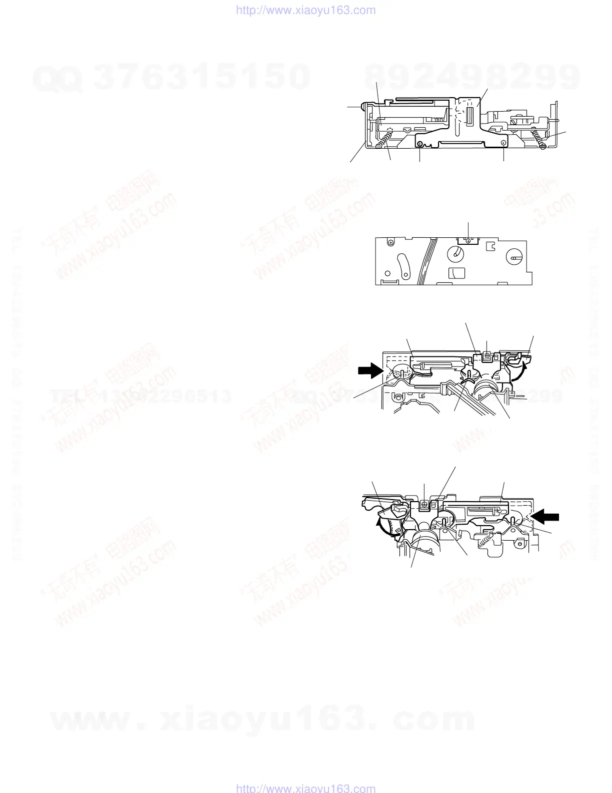
3.2.3 Removing the CD mechanism assembly
(See Fig.1, 6 to 9)
• Prior to performing the following procedure, remove the CD
mechanism control board and the front bracket (loading mo-
tor).
(1) Remove the three screws D and the damper bracket.
(2) Raise the both sides fix arms and move the fix plates in the
direction of the arrow to place the four shafts g as shown in
Fig.8 and 9.
(3) Remove the CD mechanism assembly and the two springs
h attaching the flame.
(4) Remove the two screws E and both sides rear damper
brackets from the dampers. Detach the CD mechanism as-
sembly from the left side to the right side.
ATTENTION:
The CD mechanism assembly can be removed if only the rear
damper bracket on the left side is removed.
Fig.6
Fig.7
Fig.8
Fig.9
D
D
Damper bracket
CD mechanism
assembly
Flame
h
h
D
D
Fix plate (L)
g
g
Rear damper bracket
Fix arm (L)
Damper
E
Rear damper bracket
Fix arm (R)
Damper
Fix plate(R)
E
g
g
w
w
w
.
x
i
a
o
y
u
1
6
3
.
c
o
m
Q
Q
3
7
6
3
1
5
1
5
0
9
9
2
8
9
4
2
9
8
T
E
L
1
3
9
4
2
2
9
6
5
1
3
9
9
2
8
9
4
2
9
8
0
5
1
5
1
3
6
7
3
Q
Q
TEL 13942296513 QQ 376315150 892498299
TEL 13942296513 QQ 376315150 892498299
http://www.xiaoyu163.com
http://www.xiaoyu163.com
 Loading...