1-20 (No.YA712<Rev.002>)
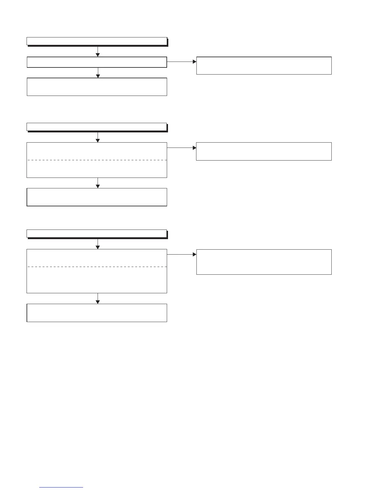
Picture does not appear normally.(S-Video input)
FLOW CHART NO.5
Are the video signal o
utputted to the Pin(6, 8) of
CN302?
Check the line between Pin(6, 8) of CN302 and
JK751, and service it if defective.
Check the line between Pin(26, 28) of CN302 and
Pin(10, 11) of TU301, and service it if defective.
Ye s
No
No
Picture does not appear normally.(Tuner input)
FLOW CHART NO.4
Are the DIF signal inputted to the Pin(26,28) of CN302?
Ye s
Replace Digital Main PWB Unit
or LCD Module
Assembly.
Replace Digital Main PWB Unit or LCD Module
Assembly.
Pin(6): S-VIDEO-C
Pin(8): S-VIDEO-Y
Picture does not appear normally.(Y/Pb/Pr input)
FLOW CHART NO.6
Are the video signal inputted to the Pin(15, 17, 19) of
CN302?
Check the line between Pin(15, 17, 19) of CN302
and input terminals(JK731, JK732, JK733), and
service it if defective.
Ye s
No
Replace Digital Main
PWB Unit or LCD Module
Assembly.
Pin(15): VIDEO-Y
Pin(17): VIDEO-Pb
Pin(19): VIDEO-Pr

 Loading...