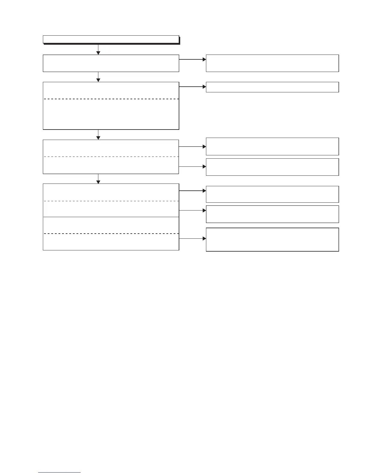
(No.YA712<Rev.002>)1-23
Ye s
Audio is not outputted normally.(Tuner input)
FLOW CHART NO.3
Are the DIF signals outputted to the Pin(26, 28)
of CN302?
Check TU301 and their periphery circuit, and
service it if defective.
No
Are the audio(L/R) signals inputted to each pin of
CN301?
Replace Digital Main PWB Unit.
No
Check SP801,SP802 and their periphery circuit,
and service it if defective.
Are the audio(L/R) signals inputted to the Pin(1, 44)
of IC801?
Are the audio(L/R) signals inputted to the Pin(3, 5)
of IC871?
Ye s
Ye s
No
No
Are the audio(L/R) signals outputted to the Pin(1, 2)
of CN801 and CN80
2?
Are the audio(L/R) signals outputte
d to the audio
output terminal?
Check IC801 and their periphery circuit, and
service it if def
ective.
CN802: SP(L)
CN801: SP(R)
JK871: AUDIO(L)-OUT
JK872: AUDIO(R)-OUT
No
Ye s
Check the line between Pin(6, 8) of CN301 and
Pin(1, 44) of IC801, and
service it if de
fective.
Check the line between Pin(2, 4) of CN301 and
Pin(3, 5) of IC871, and service it if de
fective.
No
Check the line between Pin(1, 7) of IC871 and audio
output terminal(JK871, JK872), and service it if
defective.
Pin(6) :
Pin(8) :
Pin(2) :
Pin(4) :
AMP(L)-OUT
AMP(R)-OUT
AUDIO(L)-OUT
AUDIO(R)-OUT

 Loading...