1-4 (No.YA712<Rev.002>)
SECTION 2
SPECIFIC SERVICE INSTRUCTIONS
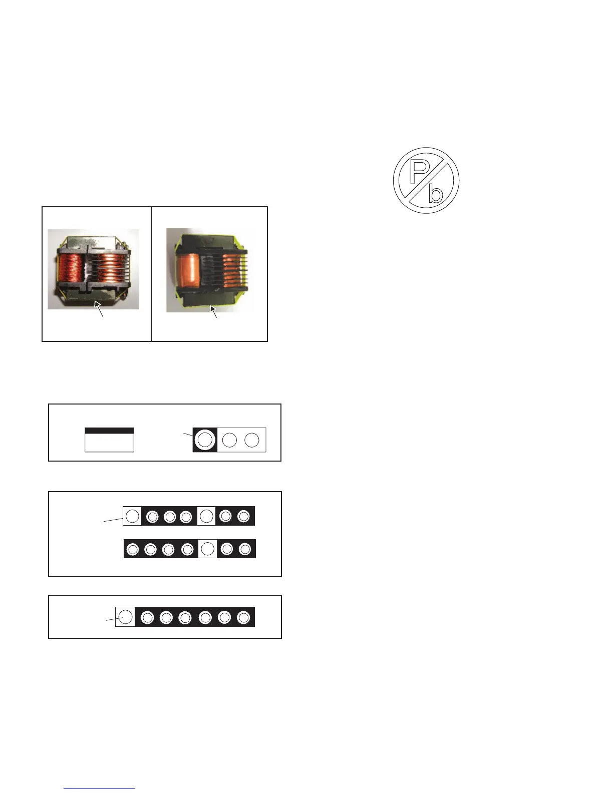
2.1 HOW TO IDENTIFY THE TRANS INVERTER
When you replace one of the below Trans Inverters on INVERT-
ER PWB, please replace with the one that has same parts num-
ber.
For the part FU-LTZ3PZDAR007, in addition to the lot number,
the letter “DARFON 7609A” is printed on the bottom of the part.
For the part FU-LTZ3PZ0XB009, in addition to the lot number,
the letter ”3PZ0XB009 JS HVT-153” is printed on the bottom of
the part.
Do not mix different parts number’s Trans Inverter.
2.2 STANDARD NOTES FOR SERVICING
2.2.1 CIRCUIT BOARD INDICATIONS
(1) The output pin of the 3 pin Regulator ICs is indicated as
shown.
(2) For other ICs, pin 1 and every fifth pin are indicated as
shown.
(3) The 1st pin of every male connector is indicated as shown.
2.2.2 PB (LEAD) FREE SOLDER
Pb free mark will be found on PCBs which use Pb free
solder. (Refer to figure.) For PCBs with Pb free mark, be sure
to use Pb free solder. For PCBs without Pb free mark, use
standard solder.
Part No.: FU-LTZ3PZDAR007
“
DARFON 7609A
”
Lot No. Stamp
“
3PZ0XB009 JS HVT-153
”
Lot No. Stamp
Part No.: FU-LTZ3PZ0XB009
Top View
Out
In
Bottom View
Input
5
10
Pin 1
Pin 1
Pb free mark

 Loading...