(No.MB160)1-19
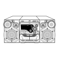
3.1.14 Removing the AUX IN board
(See Fig.32)
• Prior to performing the following procedures, remove the top
cabinet, CD changer mechanism assembly, front cabinet as-
sembly, VFD board and front board.
(1) From the inside of the front cabinet assembly, remove the
two screws Z attaching the holder.
(2) Take out the AUX IN board from the front cabinet assem-
bly.
3.1.15 Removing the phone board
(See Fig.32)
• Prior to performing the following procedures, remove the top
cabinet, CD changer mechanism assembly, front cabinet as-
sembly, VFD board and front board.
(1) From the inside of the front cabinet assembly, remove the
two screws AA attaching the holder.
(2) Take out the phone board from the front cabinet assembly.
Fig.32
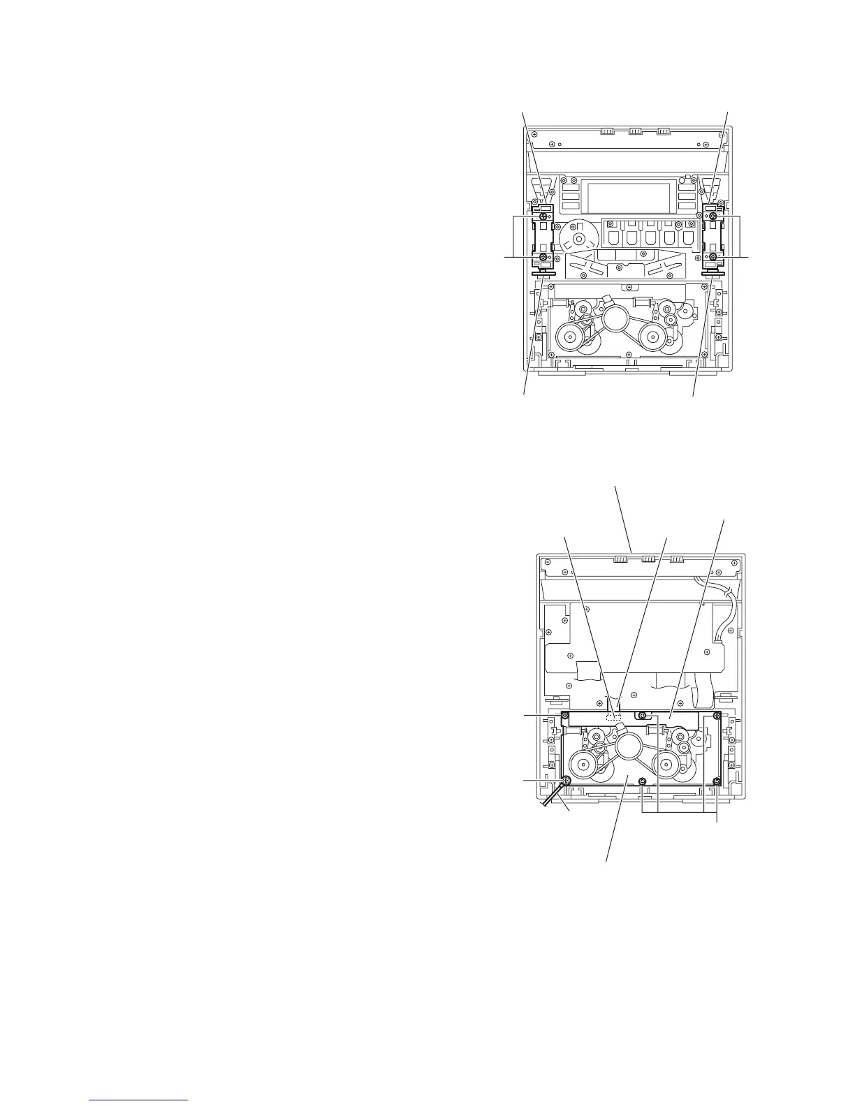
3.1.16 Removing the cassette deck mechanism assembly
(See Fig.33)
• Prior to performing the following procedure, remove the top
cabinet, CD changer mechanism assembly and front cabinet
assembly.
(1) From the inside of the front cabinet assembly, disconnect
the card wire from the connector on the mechanism board.
(2) Remove the five screws AB and screw AB’ attaching the
cassette deck mechanism assembly.
Reference:
When attaching the screw AB’, attach the earth wire with it.
Fig.33
AUX IN board
Phone board
Holder Holder
Z
AA
Front cabinet assembly
Mechanism board
Earth wire
Cassette deck mechanism assembly
Connector
AB
AB
AB'
Card wire

 Loading...