1-22 (No.MB160)
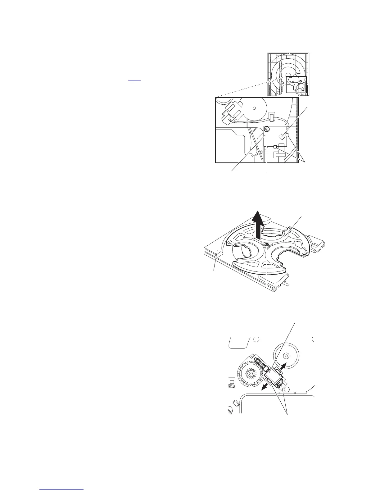
3.2.3 Removing the sensor board
(See Fig.5)
• Prior to performing the following procedures, remove the tray
disc.
(1) Remove the screw A attaching the sensor board on the
tray disc.
(2) Remove the sensor board releasing the two tabs a.
(3) Disconnect the wire from the connector CW1
on the sensor
board.
Fig.5
3.2.4 Removing the loading motor
(See Figs.6 and 7)
• Prior to performing the following procedures, remove the tray
disc and sensor board.
(1) Remove the screw B attaching the tray roulette and re-
move the tray roulette from the base tray. (See Fig.6.)
(2) Release the tabs b attaching the loading motor on the base
tray in the direction of the arrow and remove the loading
motor. (See Fig.7.)
Reference:
Base tray + Tray roulette = Tray disc
Fig.6
Fig.7
CW1
Sensor board
Tray disc (reverse side)
Tab a
A
Base tray
Tray roulette
B
Loading moto
Tabs b
Base tray (upper side)

 Loading...