(No.MB160)1-23
3.2.5 Removing the belt load, CD sub board and switch board
(See Figs.8 and 9)
• Prior to performing the following procedures, remove the tray
disc.
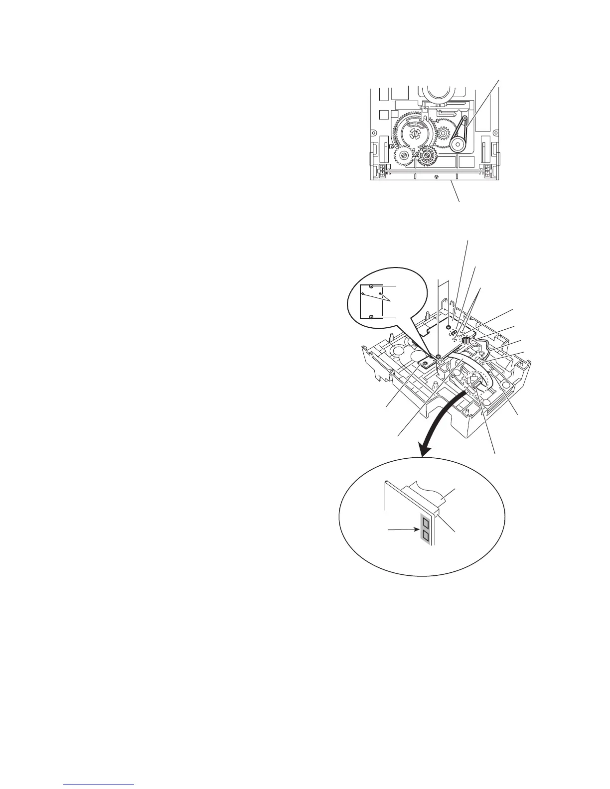
(1) Remove the belt load from the pulley on the top side of the
CD changer mechanism assembly. (See Fig.8.)
Note:
Do not strain the belt load with grease.
(2) Disconnect the card wire from the pickup unit connector on
the bottom side of the CD changer mechanism assembly.
(See Fig.9.)
Attention:
Solder is put up before the card wire is removed from the
pickup unit connector on the CD mechanism assembly.
(When the card wire is removed without putting up sol-
der, the pickup unit might destroy.) (See Fig.9.)
(3) Disconnect the wire from the connector on the CD mecha-
nism board. (See Fig.9.)
(4) Remove the two screws C attaching the CD sub board.
(See Fig.9.)
(5) Release the two tabs c and two tabs d attaching the motor
and then remove the CD sub board. (See Fig.9.)
Reference:
If the tabs c and d are hard to release, it is recommend-
able to unsolder the two soldered parts on the motor ter-
minal of the CD sub board.
(6) Remove the two screws D attaching the switch board and
take out the switch board while releasing the two tabs e at-
taching the switch board outward. (See Fig.9.)
Fig.8
Fig.9
Belt load
CD changer mechanism assembly
CD sub board
CD mechanism
board
Soldered parts
Motor
Switch board
Pickup unit connector
D
Tab s e
Tab s d
Tab s c
C
Card wire
Pickup unit
connector
Soldering
Connecto
Wire
C
Card wire

 Loading...