1-24 (No.MB160)
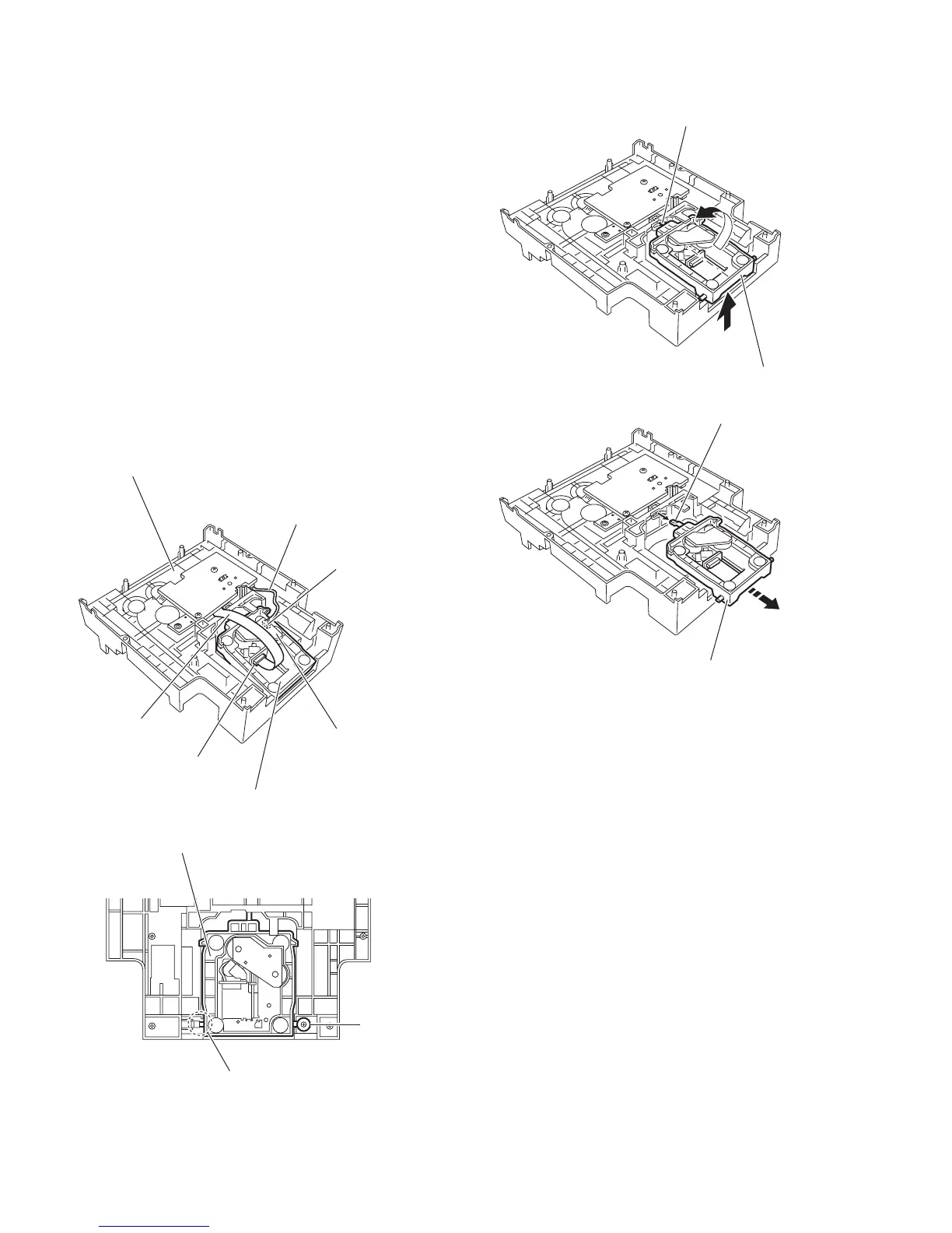
3.2.6 Removing the CD mechanism holder assembly (mechanism included)
(See Figs.9 to 13)
(1) Disconnect the wire from the connector on the CD mecha-
nism board in the CD mechanism holder assembly on the
bottom side of the CD changer mechanism assembly. (See
Fig.10.)
Attention:
Solder is put up before the card wire is removed from the
pickup unit connector on the CD mechanism assembly.
(When the card wire is removed without putting up sol-
der, the pickup unit might destroy.) (See Fig.9.)
(2) Disconnect the card wire from the pickup unit connector.
(See Fig.10.)
(3) Remove the screw E attaching the shaft on the right side of
the CD mechanism holder assembly. (See fig.11.)
(4) Pull outward the stopper fixing the shaft on the left side and
remove the CD mechanism holder assembly from behind
in the direction of the arrow. (See Figs.11 and 12.)
(5) Turn the CD mechanism holder assembly half around the
lift up slide shaft of the CD mechanism holder assembly un-
til the turntable is reversed, and pull out the CD mechanism
holder assembly. (See Figs.12 and 13.)
Fig.10
Fig.11
Fig.12
Fig.13
Connecter
CD mechanism holder assembly
CD changer mechanism assembly
Pickup unit connecter
Card wire
CD mechanism board
Wire
Stopper
CD mechanism holder assembly
E
CD mechanism holder assembly
Lift up slide shaft
CD mechanism holder assembly
Lift up slide shaft

 Loading...