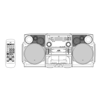
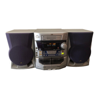
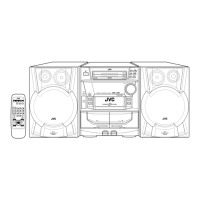
MX-J200
1-16
Removing the cam unit
(See Fig.14 ~17 )
1.
2.
3.
4.
5.
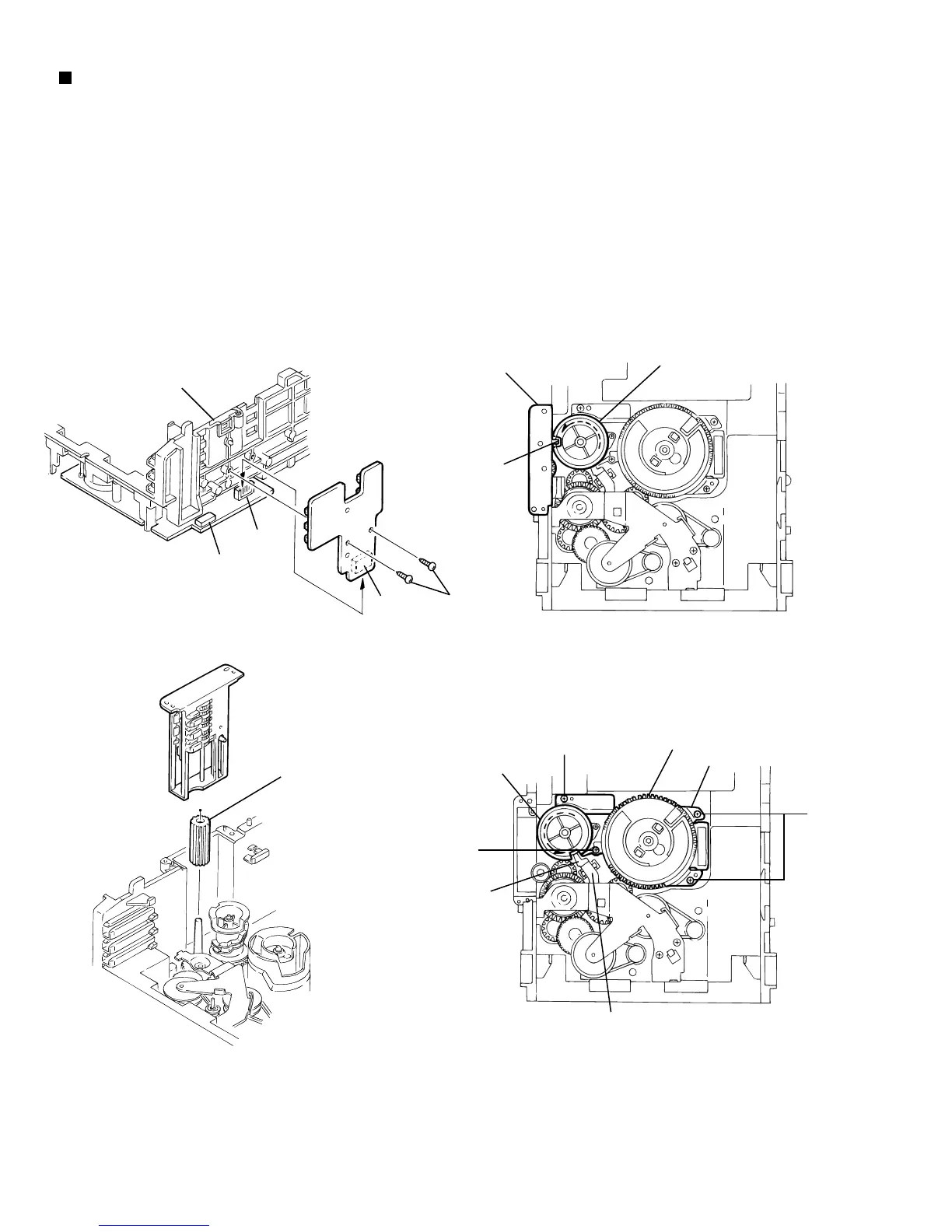
Remove the CD loading mechanism assembly.
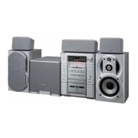
While turning the cam gear "q", align the pawl "r"
position of the drive unit to the notch position(Fig.15) on
the cam gear "q".
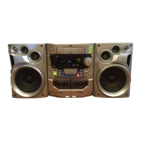
Pull out the drive unit and cylinder gear(See Fig.16).
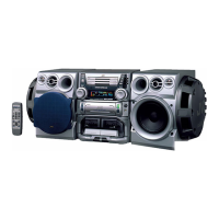
While turning the cam gear "q", align the pawl "s"
position of the select lever to the notch position(Fig.17)
on the cam gear "q".
Remove the four screws J retaining the cam unit(cam
gear "q" and cams R1/R2 assembly)(See Fig.17).
Fig.15
Fig.14
Fig.16
Cam gear
q
Drive unit
r
I
J
J
J
Chassis assembly
Tray select
switch board
CN802
CN801
CN804
Cylinder gear
Drive unit
Fig.17
Select lever
Cams R1, R2 assembly
Cam unit
Cam gear
q
s