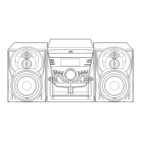
MX-K35V
1-17
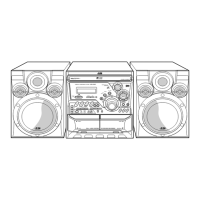
Fig.33
Prior to performing the following procedures,
remove the top cover.
Also remove the CD changer unit.
Also remove the front panel assembly.
1.
2.
3.
4.
5.
6.
Remove the five screws R that retain the cassette
deck mechanism.
Remove the cassette deck mechanism and place it
so that the front side faces up.
Remove the solder from the bottom side of the
head terminal and disconnect the wire.
Remove the screw Y that retains the head.
Loosen the screw Z that retains the head.
Hold the head and slide it in the direction of the
arrow to remove it.
Removing the cassette deck heads
(See Fig.22 and 33)
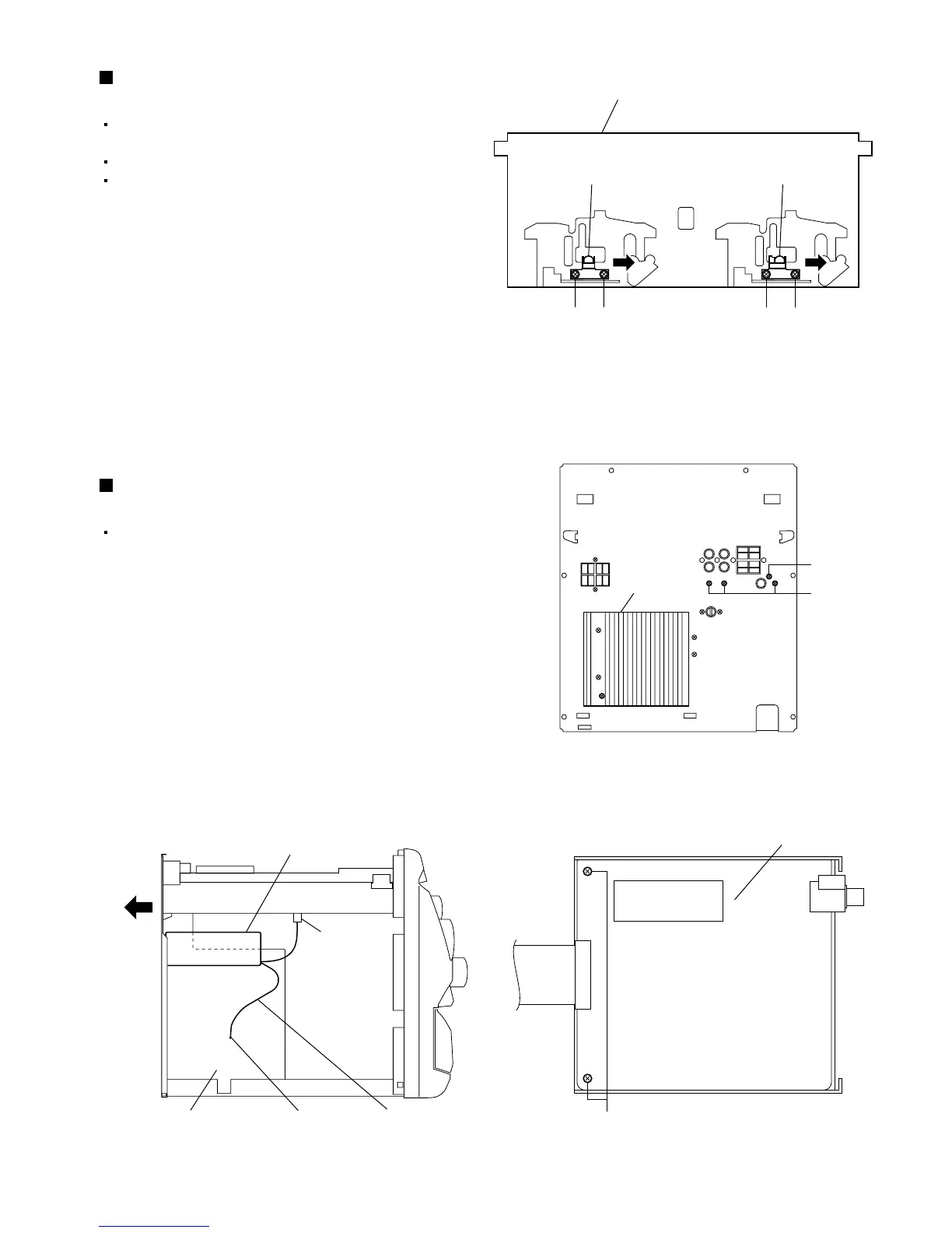
Fig.36
Prior to performing the following procedures,
remove the top cover.
1.
2.
3.
4.
5.
Disconnect the card wire from connector CN606 on
the main board.
Remove the three screws AA and screw AB
retains the Video & CD board cover.
In order to remove the wire from the Video & CD
board, remove the solder on the power amplifier
board.
Remove the Video & CD board cover.
Remove the two screws AC retains the Video & CD
board.
Removing the Video & CD board
(See Fig.2, 34 to 36)
Fig.35
Fig.34
Cassette deck mechanism
(Front side)
ZY
PB head REC/PB head
ZY
Rear
Video & CD
board cover
CN606
Heat sink
AA
AC
AB
Wire
Power amplifier board
Solder
Video & CD board
 Loading...