EasyManua.ls Logo

JVC RC-M60L - Removal of Cassette Mecha Parts

JVC RC-M60L
39 pages
Print Icon
To Next Page IconTo Next Page
To Previous Page IconTo Previous Page
Loading...
No.
1416
RC-M60L/LB
|
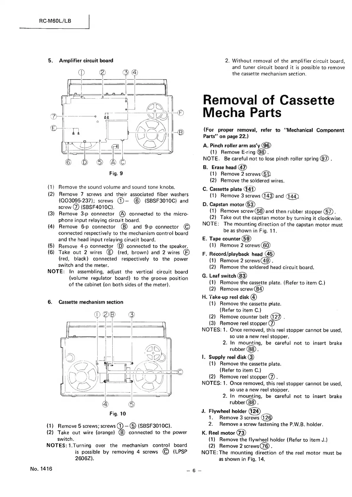
5.
Amplifier
circuit
board
(1)
Remove
the
sound
volume
and
sound
tone
knobs.
(2)
Remove
7
screws
and
their
associated
fiber
washers
(Q03095-237);
screws
(_)—
©
(SBSF3010C)
and
screw
(7)
(SBSF4010C).
(3)
Remove
3-p
connector
@)
connected
to
the
micro-
phone
input
relaying
circuit
board.
(4)
Remove
6-p
connector
and
9-p
connector
©
connected
respectively
to
the
mechanism
control
board
and
the
head
input
relaying
cirucit
board.
(5)
Remove
4-p
connector
©)
connected
to
the
speaker.
(6)
Take
out
2
wires
(©)
(red,
brown)
and
2
wires
©
(red,
black)
connected
respectively
to
the
power
switch
and
the
meter.
NOTE:
In
assembling,
adjust
the
vertical
circuit
board
(volume
regulator
board)
to
the
groove
position
of
the
cabinet
(on
both
sides
of
the
meter).
6.
Cassette
mechanism
section
O@B
©
Fig.
10
(1)
Remove
5
screws;
screws
(1)
—
G)
(SBSF3010C).
(2)
Take
out
wire
(orange)
connected
to
the
power
switch.
NOTES:
1.Turning
over
the
mechanism
control
board
is
possible
by
removing
4
screws
©
(LPSP
26062).
2.
Without
removal
of
the
amplifier
circuit
board,
and
tuner
circuit
board
it
is
possible
to
remove
the
cassette
mechanism
section,
Removal
of
Cassette
Mecha
Parts
(For
proper
removal,
refer
to
‘Mechanical
Component
Parts’’
on
page
22.)
A.
Pinch
roller
arm
assy
(1)
Remove
E-ring
;
NOTE.
Be
careful
not
to
lose
pinch
roller
spring
;
B.
Erase
head
(1)
Remove
2
screws
GD
(2)
Remove
the
soldered
wires.
C.
Cassette
plate
44D
(1)
Remove
3
screws
and
(44)
D.
Capstan
motor
63
(1)
Remove
screw
8)
and
then
rubber
stopper
G7).
(2)
Take
out
the
capstan
motor
by
turning
it
clockwise.
NOTE:
The
mounting
direction
of
the
capstan
motor
must
be
as
shown
in
Fig.
11.
E.
Tape
counter
69)
(1)
Remove
2
screws
(60)
F.
Récord/playback
head
5)
(1)
Remove
2
screws
(49)
‘
(2)
Remove
the
soldered
head
circuit
board.
G.
Leaf
switch
(1)
Remove
the
cassette
plate.
(Refer
to
item
C.)
(2)
Remove
screw
H.
Take-up
reel
disk
(1)
Remove
the
cassette
plate.
(Refer
to
item
C.)
(2)
Remove
counter
belt
2)
:
(3)
Remove
reel
stopper
(7)
NOTES:
1.
Once
removed,
this
reel
stopper
cannot
be
used,
so
use
a
new
reel
stopper.
2.
In
mounting,
be
careful
not
to
insert
brake
rubber
.
I.
Supply
reel
disk
@)
(1)
Remove
the
cassette
plate.
(Refer
to
item
C.)
(2)
Remove
reel
stopper
(7)
.
NOTES:
1.
Once
removed,
this
reel
stopper
cannot
be
used,
sO
use
a
new
reel
stopper.
2. In
mounting,
be
careful
not
to
insert
brake
rubber
:
J.
Flywheel
holder
1.
Remove
3
screws
2.
Remove
a
screw
fastening
the
P.W.B.
holder.
K.
Reel
motor
@3)
(1)
Remove
the
flywheel
holder
(Refer
to
item
J.)
(2)
Remove
2
screws(76)
.
NOTE:
The
mounting
direction
of
the
reef
motor
must
be
as
shown
in
Fig.
14.