RX-5030VBK
1-18 (No.22025)
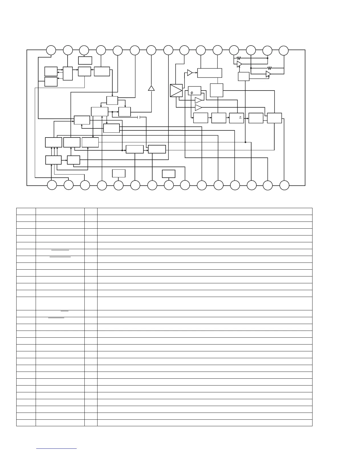
4.10 LA1838 (IC102): FM AM IF Amp. & Detector, FM MPX decoder
• Block Diagram
• Pin Function
ALC
BUFF
AM
OSC
REG
AM
MIX
FM
RF.AMP
AGC
AM IF
DET
SD
COMP
AM
S-METER
FM
S-METER
FM IF
PM
DET
S-CLRVE
AM/FM
IF-BUFF
TUNING
DRIVE
GND
VCC
STEREO
DRIVE
MUTE
DECODER
ANIT-BIRDIE
STEREO
5N
SW
P-DET
PILOT
DET
FF
19k
FF
19k
FF
38k
VCO
384KHz
/
2
/LS
30
29
28
27
26
25
24
23
22
21
20
19
18
17 16
1
2
3
4
6
7
89
10
11
12 13
14
15
5
Pin No. Symbol I/O Function
1 FM IN I This is an input terminal of FM IF signal.
2 AM MIX O This is an out put terminal for AM mixer.
3 FM IF I Bypass of FM IF
4 AM IF I Input of AM IF Signal.
5 GND - This is the device ground terminal.
6
TUNED
O When the set is tunning, this terminal becomes "L".
7
STEREO
O Stereo indicator output. Stereo "L", Mono: "H"
8 VCC - This is the power supply terminal.
9 FM DET - FM detect transformer.
10 AM SD - This is a terminal of AM ceramic filter.
11 FM VSM O Adjust FM SD sensitivity.
12 AM VSM O Adjust AM SD sensitivity.
13 MUTE I/O When the signal of IF REQ of IC121(LC72131) appear, the signal of FM/AM IF output.
//Muting control input.
14
FM/AM
I Change over the FM/AM input. "H" :FM, "L" : AM
15
MONO
/ST
O Stereo : "H", Mono: "L"
16 L OUT O Left channel signal output.
17 R OUT O Right channel signal output.
18 L IN I Input terminal of the Left channel post AMP.
19 R IN I Input terminal of the Right channel post AMP.
20 RO O Mpx Right channel signal output.
21 LO O Mpx Left channel signal output.
22 MPX IN I Mpx input terminal
23 FM OUT O FM detection output.
24 AM DET O AM detection output.
25 AM AGC I This is an AGC voltage input terminal for AM
26 AFC - This is an output terminal of voltage for FM-AFC.
27 AM RF I AM RF signal input.
28 REG O Register value between pin 26 and pin28 besides the frequency width of the input signal.
29 AM OSC - This is a terminal of AM Local oscillation circuit.
30 OSC BUFFER O AM Local oscillation Signal output.
 Loading...