RX-9010VBK
1-5
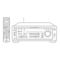
Prior to performing the following procedure, remove
the top cover and the rear panel.
Cut off the tie band fixing the harness.
Disconnect the connect CN501, CN243, CN205,
CN381, CN361 on the DVD board.
Disconnect the harness from connector CN721,
CN722 and CN723 on the main board.
Disconnect the harness from connector CN1 on the
antenna unit and remove the antenna unit.
Disconnect the harness from connector CN491 on
the relay board.
Disconnect the tuner board and audio board from
connector CN101 and CN301 on the audio board.
Pull out the video audio board, video board, S-video
board.
Disconnect the DSP board from connector CN601 on
the audio board.
1.
2.
3.
4.
5.
6.
7.
8.
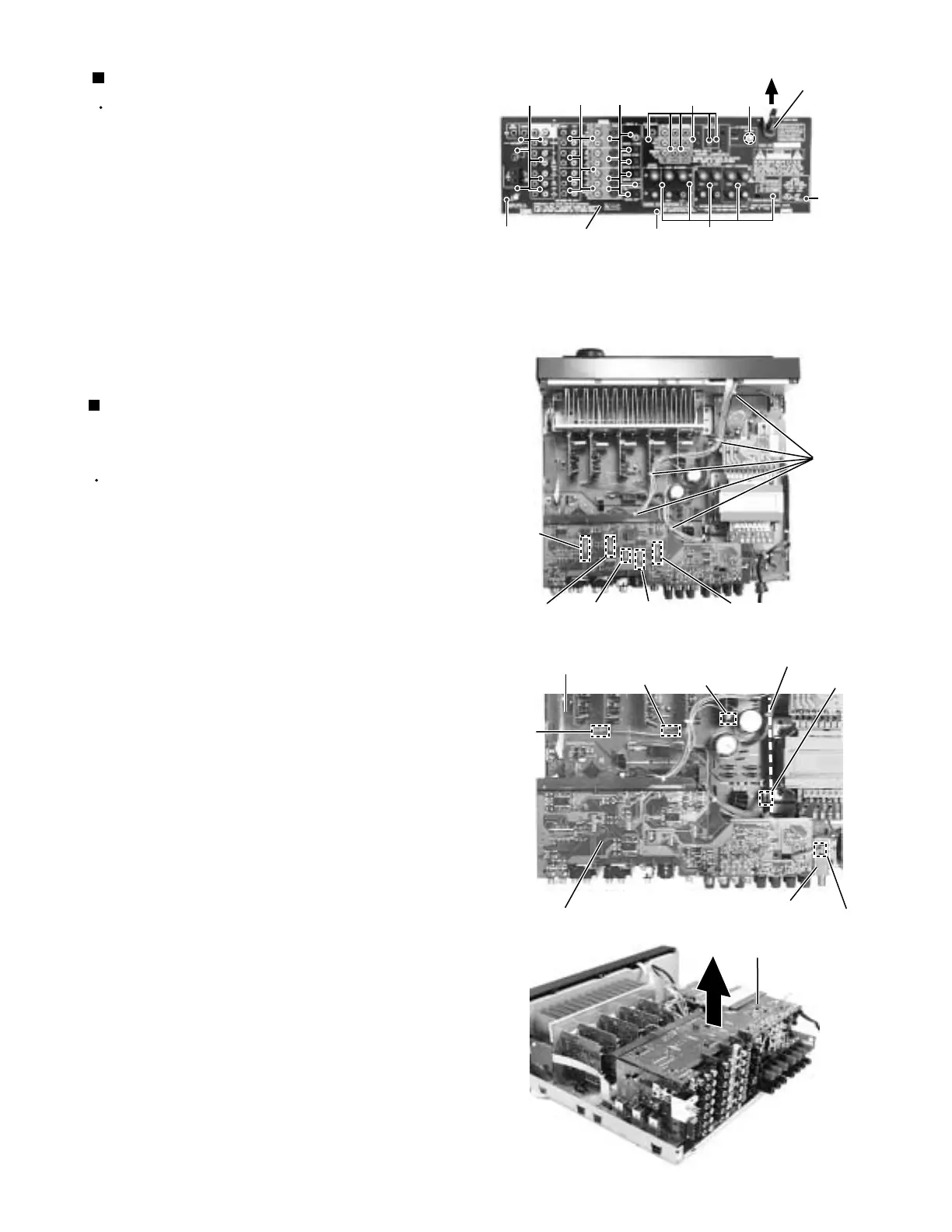
Removing each board connected to the
rear side of the audio board
(See Fig.6 to 12)
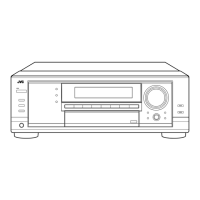
Prior to performing the following procedure, remove
the top cover.
Remove the power cord stopper from the rear panel
by moving it in the direction of the arrow.
Remove the thirty five screws E and a hexagon nut b
attaching the each boards to the rear panel on the
back of the body.
Remove the three screws F attaching the rear panel
on the back of the body.
1.
2.
3.
Removing the rear panel (See Fig.5)
Fig.6
Fig.7
Tie band
CN723
CN361
CN381 CN243
CN501
CN721
CN722
CN205
Fig.8
DVD board
CN1
Main board
Antenna unit
CN491
Relay board
Fig.5
E
FEF
F
Cord stopper
Rear panel
EEEb
DVD board
 Loading...