1-16 (No.22008)
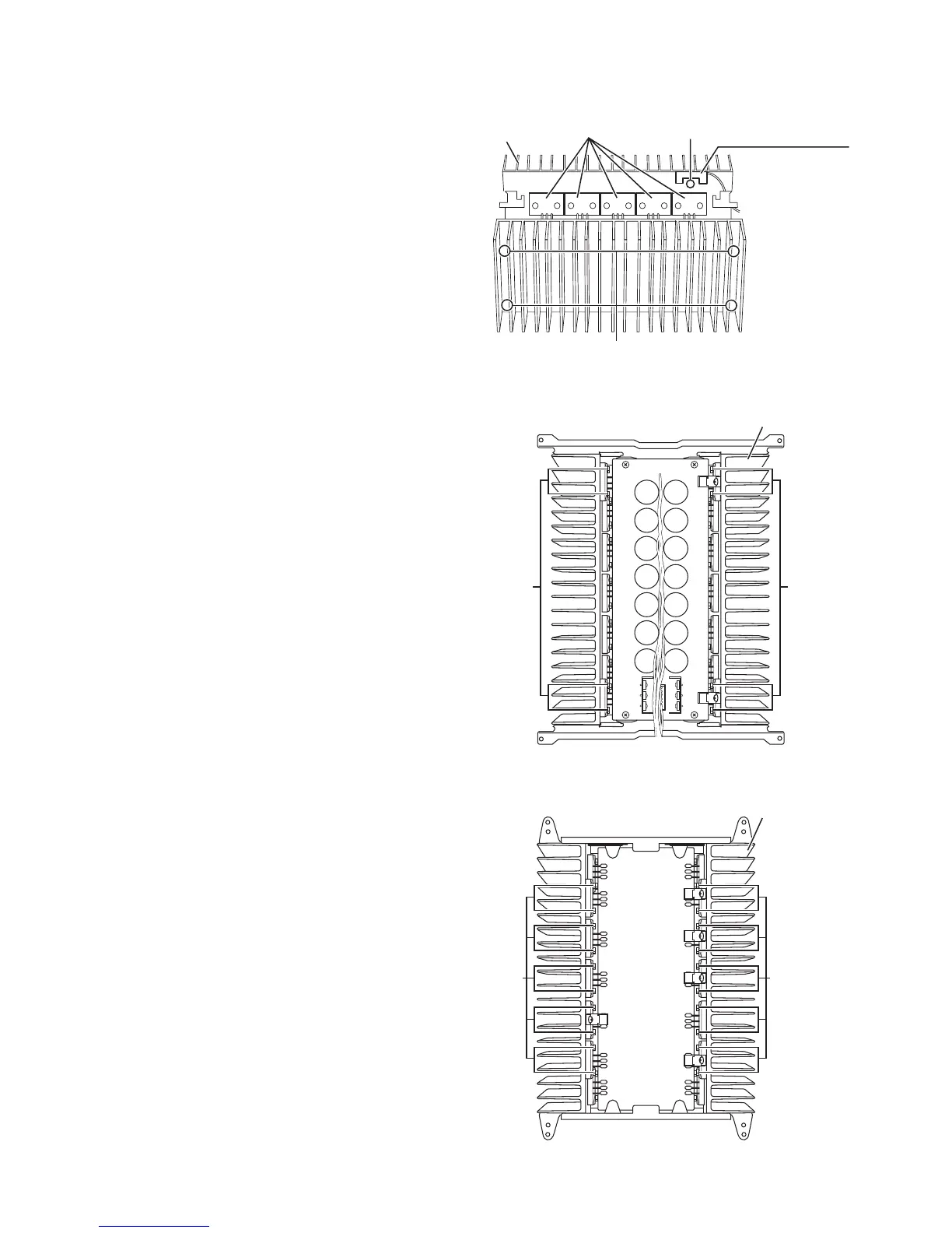
3.2.2 Removing the thermal SW 2 board
(See Fig.4)
• Prior to performing the following procedure, remove the power
amp. assembly, relay board and each amp. board of Lch, Cch,
SL/SRch, Rch.
(1) Remove the screw B attaching the thermal SW 2 board.
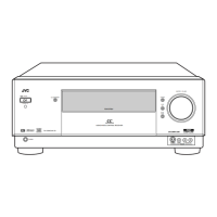
3.2.3 Removing the heat sink
(See Fig.4 to 6)
• Prior to performing the following procedure, remove the power
amp. assembly, relay board and each amp. board of Lch, Cch,
SL/SRch, Rch.
(1) Remove the eight screws C attaching the heat sink on the
both sides of the power amp. assembly.
(2) Remove the eight screws D attaching the power ICs (top
side).
(3) Remove the twenty screws D attaching the power ICs (bot-
tom side).
Fig.4
Fig.5
Fig.6
C (both sides)
B
Heat sink
Power ICs
Thermal SW 2 board
bottom side
Heat sink
top side
DD
DD
Heat sink
bottom side