(No.22008)1-7
SECTION 3
DISASSEMBLY
3.1 Main body section
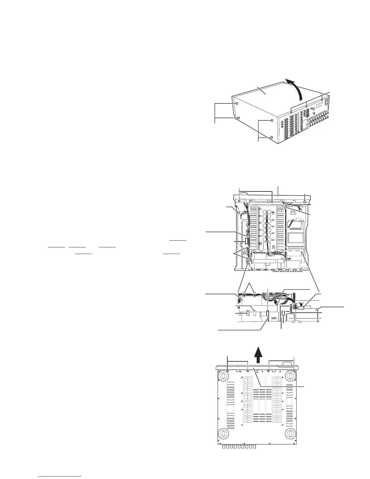
3.1.1 Removing the top cover
(See Fig.1)
(1) Remove the eight screws A attaching the top cover on both
sides of the body.
(2) Remove the three screws B on back of the body.
(3) Remove the top cover from behind in the direction of the ar-
row while pulling both sides outward.
Fig.1
3.1.2 Removing the front panel assembly
(See Fig.2 and 3)
• Prior to performing the following procedure, remove the top
cover.
(1) Cut off the tie band 1 fixing the harness.
(2) Remove the screw a, and remove the lug wire.
(3) Remove the three screws C attaching the front panel as-
sembly.
(4) Remove the four screws D attaching the front panel as-
sembly on bottom of the body. Detach the front panel as-
sembly toward the front.
(5) Disconnect the harness from the connector CN971
,
CN977
, CN983 and CN985 on the system control board
(see fig.5), CN973 on the front AV in board and CN373 on
the front DIGITAL board (see 2-3.Front panel assembly
section/ fig.2).
Fig.2
Fig.3
(both sides)
A(both sides)
B
Top cover
C
a
(fixing the
lug wire)
Tie band 1
Harness
band
Tuner unit
Compu
link board
Audio 7.1ch
in board
V compo 2 board
Y/C separator
board
RF remote unit
CN1
CN1
C
Front panel assembly
CN581
CN481
CN482
CN301
CN201
Tie band 2
Tie band 3
Audio signal
1 board
D
D
Front panel
assembly