1-8 (No.22008)
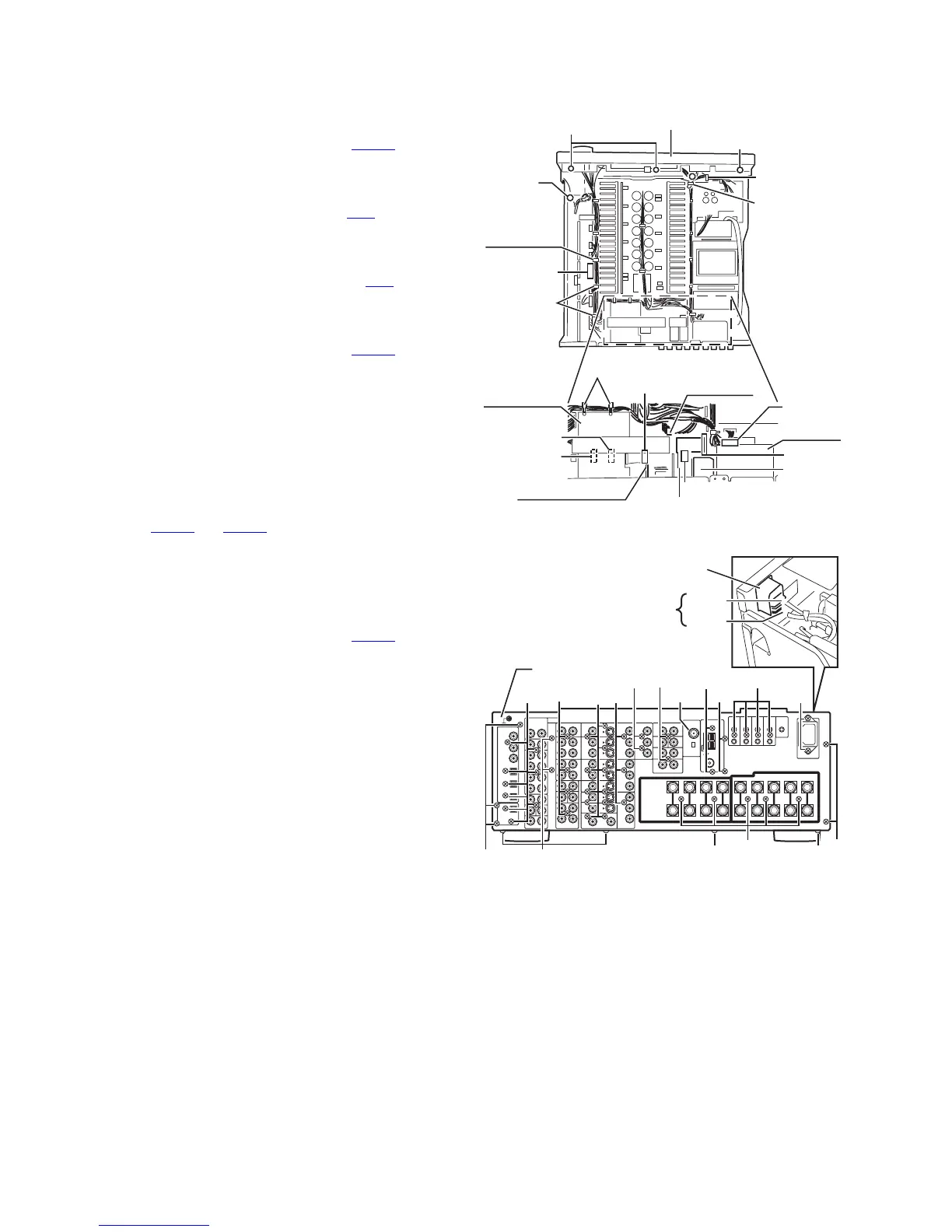
3.1.3 Removing the V compo 2 board & RF remote unit & tuner unit & compu link board
(See Fig.2 and 4)
• Prior to performing the following procedure, remove the top
cover.
(1) Disconnect the harness from the connector CN581 on the
V compo 2 board.
Remove the two screws E' attaching the V compo 2 board
to the rear panel.
(2) Disconnect the harness from the connector CN1
on the RF
remote unit.
Remove the nut b attaching the RF remote unit to the rear
panel.
(3) Disconnect the card wire from the connector CN1
on the
tuner unit.
Remove the two screws E'' attaching the tuner unit to the
rear panel.
(4) Disconnect the harness from the connector CN301
on the
compu link board.
Remove the four screws E''' attaching the compu link
board to the rear panel.
3.1.4 Removing the Y/C separator board
(See Fig.2)
• Prior to performing the following procedure, remove the top
cover.
(1) Cut off the tie band 2 fixing the harness.
(2) Draw out up the Y/C separator board, disconnecting the
connectors CN481
and CN482 on the Y/C separator board.
3.1.5 Removing the audio 7.1ch in board
(See Fig.2 and 4)
• Prior to performing the following procedure, remove the top
cover.
(1) Cut off the tie band 2 & 3 fixing the harness.
(2) Disconnect the harness from the connector CN201
on the
audio signal 1 board.
(3) Remove the two screws E'''' attaching the audio 7.1ch in
board to the rear panel.
3.1.6 Removing the rear panel
(See Fig.4)
• Prior to performing the following procedure, remove the top
cover.
(1) Unsolder the two solder parts on the AC inlet.
(2) Remove the forty four screws E & E' & E'' & E''' & E'''' and
the nut b attaching each board to the rear panel.
(3) Remove the thirteen screws F attaching the rear panel on
the back of the body and bottom.
Fig.2
Fig.4
C
a
(fixing the
lug wire)
Tie band 1
Harness
band
Tuner unit
Compu
link board
Audio 7.1ch
in board
V compo 2 board
Y/C separator
board
RF remote unit
CN1
CN1
C
Front panel assembly
CN581
CN481
CN482
CN301
CN201
Tie band 2
Tie band 3
Audio signal
1 board
b
E
F
E'''
E
FF
F
F
Rear panel
Red
Black
E
E
E''
E''''
E'
E
E
F
Solder part
AC inlet