1-16 (No.82996)
5.2.3 Details of the OSD display in the EMG display mode
During the EMG display, the OSD shows the data on the deck
mode, etc. The details of the display contents are as follows.
Notes:
• The display is variable depending on the part No. of the
System Control microcomputer (IC3001) built into the
VCR. In the following, refer to the figure carrying the
same two characters as the top two characters of the
part number of your IC.
• The sensor information in the OSD display contents is
partially different from the mechanism sensor informa-
tion in EMG detail information < 1 >.
[For MN* only]
*FF:Sensor information details
[For *HD only]
*DD:Sensor information details
[For both MN*/HD*]
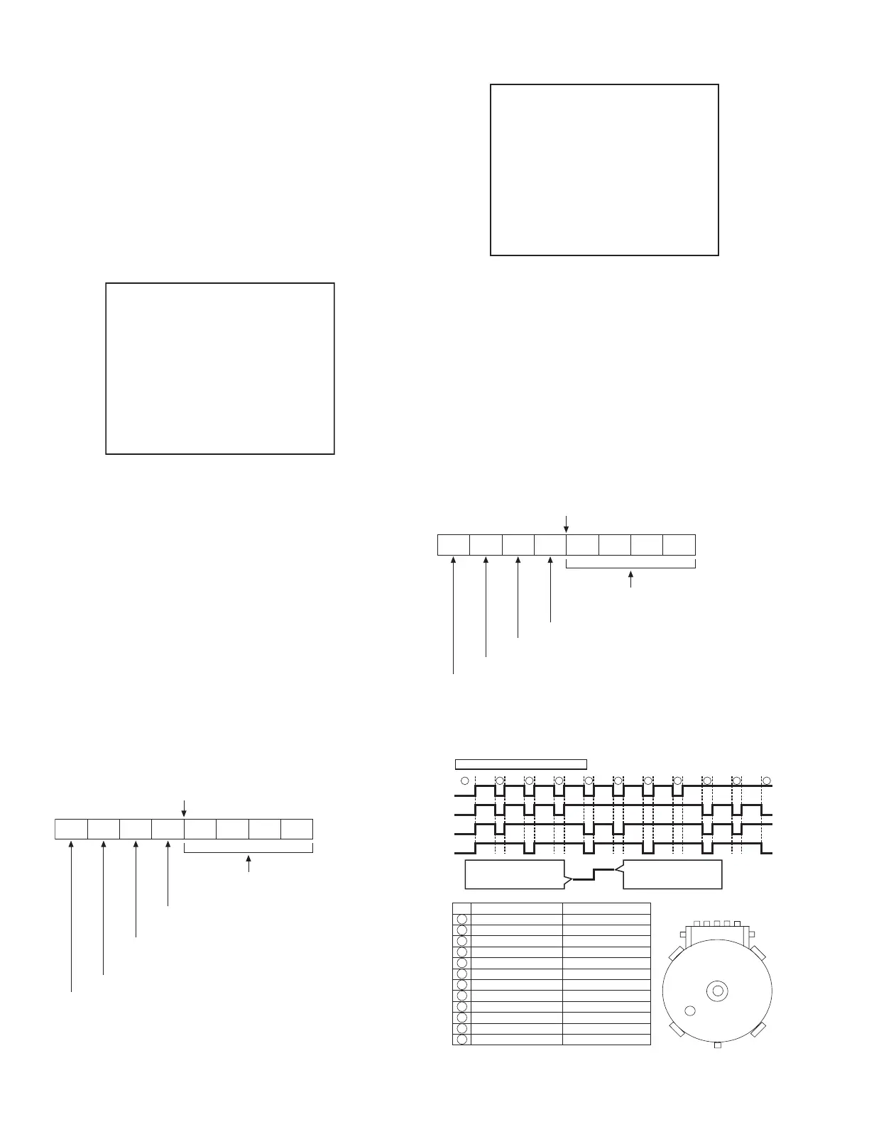
Mechanism mode sequence
AA : Deck operation mode (See EMG detail information < 1 >.)
BB : Mechanism operation mode
(See EMG detail of information < 1 >.)
CC : Mechanism transition flag
DD : Capstan motor control status
EE : Loading motor control status
FF : Sensor information (See sensor information details.)
GG : Capstan motor speed
HH : Key code (JVC code)
I I : Supply reel winding diameter data, higher 8 bits.
JJ : Supply reel winding diameter data, lower 8 bits.
KK : Mechanism sensor information & mechanism mode
position(See EMG detail of information < 1 >.)
LL : Tape speed data, higher 8 bits.
MM : Tape speed data, lower 8 bits.
NN : Cassette tape type < 2 >, higher 8 bits.
(See EMG detail of information < 2 >.)
OO : Cassette tape type < 2 >, lower 8 bits.
(See EMG detail of information < 2 >.)
PP : General data display area
YY : General data display area
AA BB CC DD EE
FF GG HH I I J J
KK L L MM NN OO
PP QQ RR SS T T
UU VV WW XX YY
<Display>
** h
********
Encoder data
(See Mechanism mode sequence.)
Cassette tab present = 1
Cassette tab broken = 0
Cassette absent = 1
Cassette present = 0
Start sensor
End sensor
AA : Key code (JVC code)
BB : Deck operation mode(See EMG detail information < 1 >.)
CC : Mechanism operation mode (See EMG detail information
< 1 >.)
DD : Sensor information (See sensor information details.)
EE : Capstan motor speed (Search, double speed)
FF : Tracking value
GGGG : Cassette tape type < 2 >, 16 bits.
(See EMG detail information < 2 >.)
HHHH : Supply reel winding diameter data
I I : Capstan motor speed (FF/REW, double speed)
JJJJ : Tape speed data, lower 8 bits.
KKKK : General data display area
LLLL : General data display area
MMMM : General data display area
AA BB CC
DD EE FF
GGGG HHHH
I I JJJJ
KKKK LLLL MMMM
ROM No.
<Display>
** h
********
Encoder data
(See Mechanism mode sequence.)
Remote pause
End sensor
Start sensor
Cassette tab present = 1
Cassette tab broken = 0
LSA
LSB
LSC
LSD
Encoder output = Low
or
Trerminal - GND = SHORT
Encoder output = High
or
Trerminal - GND = OPEN
Mechanism mode - Encoder data
1110
9876
543
21
No. Position Encoder data
EJECT 0 h = 0000
EJECT1 1 h = 0001
EJECT2 2 h = 0010
ULSTOP 3 h = 0011
UPPER 4 h = 0100
ONSTOP(PLAY) 5 h = 0101
FWD/SS 6 h = 0110
REV/SS 7 h = 0111
OFFSTOP 8 h = 1000
FFREW-BRAKE 9 h = 1001
FFREW A h = 1010
MIDDLE F h = 1111
1
2
3
4
5
6
7
8
9
10
11
12
LSD
LSC
LSB
LSA
GND
12345
www.freeservicemanuals.info

 Loading...