2-33
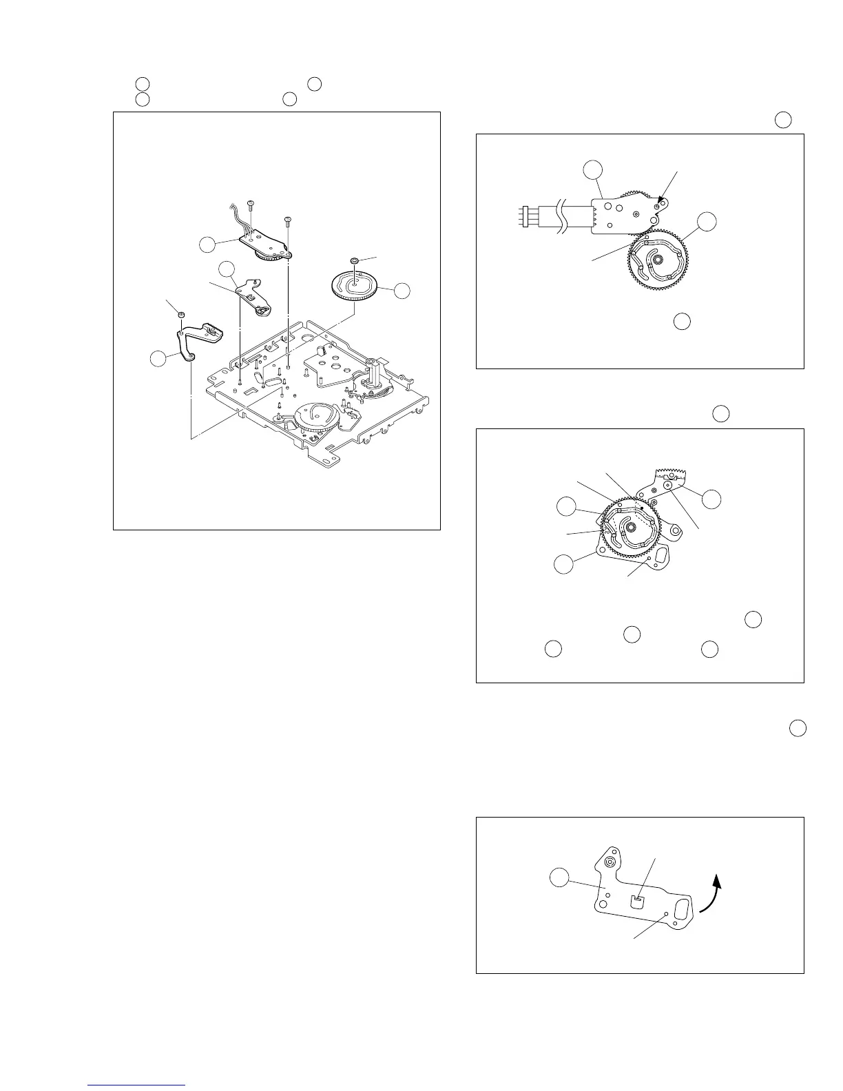
13.
34
Rotary encoder assembly /
35
Main cam /
36
Arm gear 1 assembly /
37
Centering arm assembly
Fig. 2-13-13
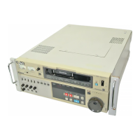
<Note 14> :
How to attach the rotary encoder assembly 34 .
Fig. 2-13-13A
Fig. 2-13-13B
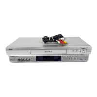
<Note 15> : How to attach the main cam 35 .
Fig. 2-13-13C
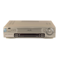
<Note 16> :
How to remove the centering arm assembly 37
The center arm assembly is located behind the
mechanism assembly when the phase is
aligned correctly. The center arm assembly can
be removed by displacing it in the direction of
the arrow.
30
(
S2
)
34
(
L18
)
37
36
35
(
W1
)
29
(
S2
)
<Note14>
<Note15>
<Note16>
<Note15>
<Note15>
COLLAR
34
35
Phase alignment
Mark (colored : red)
35
37
36
Phase alignment
Phase alignment
Phase alignment
Boss
Boss
Align the phase of the main cam 35 , then attach it by
placing the (red) coloured markings (on 2 gear teeth)
within the encircled area.
Phase alignment
L18
37
Align the phases of the arm gear 1 assembly 36 and
centering arm assembly 37 , then attach the arm gear 1
assembly 36 /centering arm assembly 37 by fitting the
bosses into the lower cam slot, and fit the slit washer.