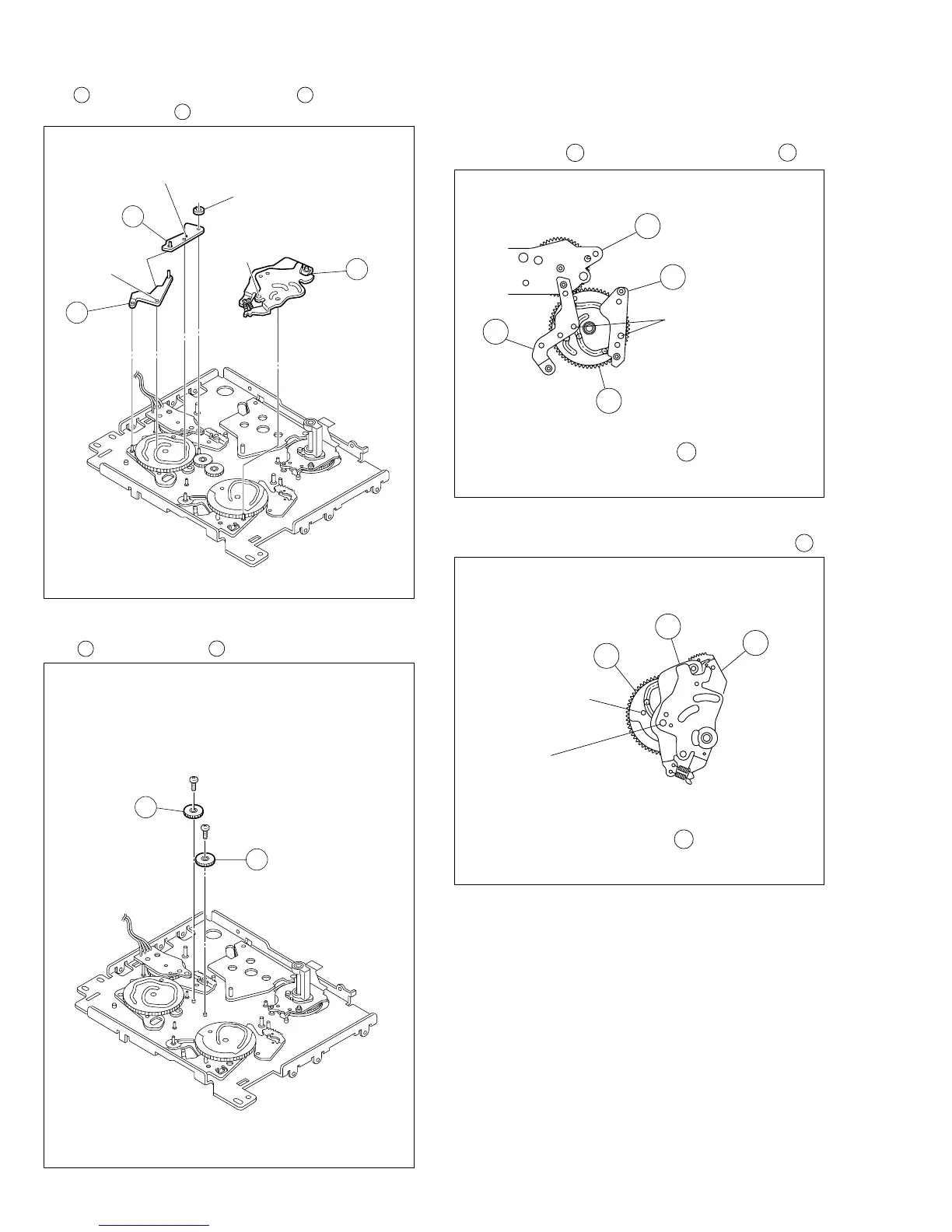
2-32
11.
29
Tension control arm assembly/
30
Brake control
arm assembly /
31
Charge arm assembly
Fig. 2-13-11
Fig. 2-13-12
<Note 12> : How to attach the tension control arm assem-
bly 29 / Brake control arm assembly 30 .
12.
32
Connect gear 2 /
33
Connect gear 2
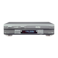
Fig. 2-13-11A
Align the phase of the main cam 35 , then attach it by
fitting the bosses into the cam slot.
<Note 13> : How to attach the charge arm assembly 31 .
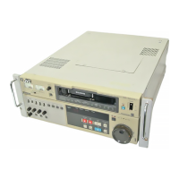
Fig. 2-13-11B
Align the phase of the sub cam 38 , then attach it by
fitting the boss into the cam slot.
(
L17
)
29
30
31
(
L16
)
(
L15
)
(
W1
)
<Note12>
<Note13>
34
30
29
35
Boss
(Phase alignment)
38
31
39
Boss
(Phase alignment)
Phase alignment
27
(
S2
)
33
28
(
S2
)
32