1-10 (No.MB623)
3.1.7 Removing the POWER BOARD assembly
(See Fig.14 to 17)
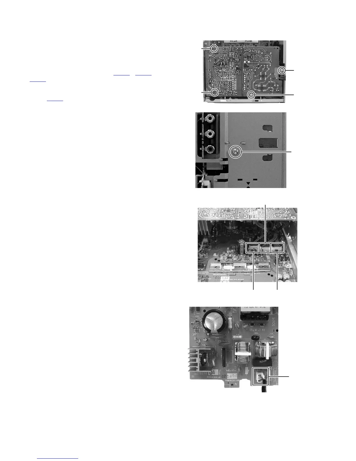
(1) Remove the four screws M attaching the POWER BOARD
assembly. (See Fig.14)
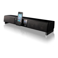
(2) Remove the one screw N attaching the DUMMY BOARD.
(See Fig.15)
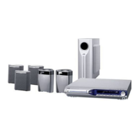
(3) Disconnect the connector wires from POWER BOARD as-
sembly connected to connector CN200
, CN201 and
CN202
of the MAIN BOARD assembly. (See Fig.16)
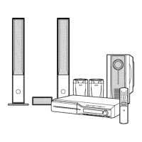
(4) Lift up the POWER BOARD assembly with POWER
CORD, and then disconnect the POWER CORD from con-
nector CN101
of the POWER BOARD assembly. (See
Fig.17)
Fig.14
Fig.15
Fig.16
Fig.17
M
M
M
M
N
CN200
CN201
CN202
CN101