EasyManua.ls Logo

JVC TH-L1A

JVC TH-L1A
51 pages
To Next Page IconTo Next Page
Loading...
SERVICE MANUAL
COPYRIGHT © 2007 Victor Company of Japan, Limited
No.MB623
2007/7
DIGITAL MEDIA SYSTEM
MB62320077SERVICE MANUAL
TH-L1A, TH-L1US, TH-L1UB,
TH-L1UJ, TH-L1UG, TH-L1UN
COPYRIGHT © 2007 Victor Company of Japan, Limited
Lead free solder used in the board (material : Sn-Ag-Cu, melting point : 219 Centigrade)
Lead free solder used in the board (material : Sn-Cu, melting point : 230 Centigrade)
TABLE OF CONTENTS
1 PRECAUTION. . . . . . . . . . . . . . . . . . . . . . . . . . . . . . . . . . . . . . . . . . . . . . . . . . . . . . . . . . . . . . . . . . . . . . . . . 1-4
2 SPECIFIC SERVICE INSTRUCTIONS . . . . . . . . . . . . . . . . . . . . . . . . . . . . . . . . . . . . . . . . . . . . . . . . . . . . . . 1-5
3 DISASSEMBLY . . . . . . . . . . . . . . . . . . . . . . . . . . . . . . . . . . . . . . . . . . . . . . . . . . . . . . . . . . . . . . . . . . . . . . . 1-5
4 ADJUSTMENT . . . . . . . . . . . . . . . . . . . . . . . . . . . . . . . . . . . . . . . . . . . . . . . . . . . . . . . . . . . . . . . . . . . . . . . 1-14
5 TROUBLESHOOTING . . . . . . . . . . . . . . . . . . . . . . . . . . . . . . . . . . . . . . . . . . . . . . . . . . . . . . . . . . . . . . . . . 1-14
AX-THL1
SP-THL1W
SP-THL1F
SP-THL1F
SP-THL1C
SP-THL1S
SP-THL1S
Question and Answer IconNeed help?

Do you have a question about the JVC TH-L1A and is the answer not in the manual?

JVC TH-L1A Specifications

General IconGeneral
BrandJVC
ModelTH-L1A
CategoryHome Theater System
LanguageEnglish

Summary

PRECAUTION

Safety Precautions

Essential safety guidelines for product handling and repair.

Warning Notices

Information on adherence to safety standards and repairer responsibility.

Cautionary Notes

Advice regarding potential chassis burrs during system repair.

Critical Safety Component Identification

Guidance on identifying and replacing safety-critical parts.

DISASSEMBLY

Removing the Side Panel

Procedure for removing the side panel assembly.

Removing the Front Panel Assembly

Steps to detach the front panel, including connections.

Removing the Top Chassis

Instructions for disassembling the top chassis.

Removing the HDMI Assembly

Procedure for disconnecting and removing the HDMI board.

Removing the Video 2 Board Assembly

Steps to detach the Video 2 board and its connections.

Removing the Heat Sink

Instructions for removing the heat sink assembly.

Removing the Power Board Assembly

Procedure for detaching the power board assembly.

Removing the Rear Panel

Guide for removing the rear panel and its connectors.

Removing the DSP Board Assembly

Steps to disconnect and remove the DSP board assembly.

Removing the Main Board Assembly

Procedure for detaching the main board assembly.

Removing the Front Board Assembly

Instructions for removing the front board assembly.

ADJUSTMENT

Extension Cable Usage

Guidance on using extension cables for operation checks.

Special Mode Operations

Details on entering and using special modes for diagnostics.
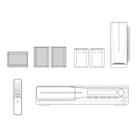
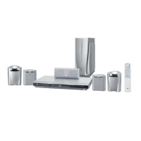
Related product manuals