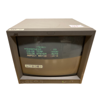
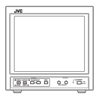
TM-H140PN
The three adjustments NTSC SUB CHROMA, NTSC SUB PHASE and PAL SUB CHROMA described in this page are basic
adjustments for another three adjustments NTSC 3.58 CHROMA, NTSC 3.58 PHASE, PAL CHROMA and PAL PHASE described
in a subsequent page. The adjustments shall be done by using component parts such as semi-fixed type VR. Both
adjustments in this page and the subsequent page should be always done at the same time and in accordance with the
specified order. Note that unilateral adjustments should be avoided.
Item Test equipment Test points
Adjustment
locations
NTSC Signal generator
SUB CHROMA (NTSC full colour
TP-B : S4 (§)pin SUB COLOUR VR
[INPUT PWB
Adjustment bar)
NTSC
SUB PHASE
Adjustment
Oscillo-scope
W (75%)
----~-------··-··· ··--t--
Cy
Mg
y
G
-
R
(A)
--'-·
B
LJ
Signal generator TP-B : S4 @ pin SUB PHASE VR
(NTSC full colour bar) [INPUT PWB]
Oscillo-scope
Mg
B
y
G
R
s
PAL Signal generator
TP-CR: S4 (Z)pin SUB COLOUR VR
[INPUT PWB]
SUB CHROMA (PAL full colour bar)
Adjustment Oscillo-scope
_J~. T
(C)
s- ............ L
I
No.51766
Adjustment procedure
• Colour synchronisation adjustment (NTSC &
PAL) have been finished .
• PAL lissajous adjustment have been finished.
1. Input the NTSC full colour bar.
2. Connect the oscillo-scope to TP-B.
3. Adjust the SUB COLOUR VR to bring the
voltage of (A) in the illustration to 0±40mV .
4. Input the NTSC full colour bar.
5. Connect the oscillo-scope to TP-B.
6. Adjust the SUB PHASE VR to bring the voltage
of {B) in the illustration to 0±40mV.
7. Input the PAL full colour bar.
8. Connect the oscillo-scope to TP-CR.
9. Adjust the SUB COLOUR VR to bring the
voltage of {C) in the illustration to 500±20mV.
27
 Loading...